A mill that suddenly needs more power to produce the same tonnage of cement is rarely a mill problem at all — it's usually a separator quietly losing its edge. Fine particles that should exit as finished product get pulled back into the mill for another pass, burning energy on material that was already ground correctly the first time. Circulating load creeps up, specific power consumption climbs, and most plants don't catch it until a quarterly energy review flags the trend. Book a demo to see separator performance tracked continuously instead of once a quarter.
Your Separator Is Either Saving Energy Every Second — Or Wasting It Every Second
A dynamic classifier has no idle state. It is either sharply separating fines from coarse material on every pass, or it's sending already-fine particles back through the mill for a second, energy-wasting grind. There is no middle ground, only degrees of loss.
First-Generation to Third-Generation Separators — What Actually Changed
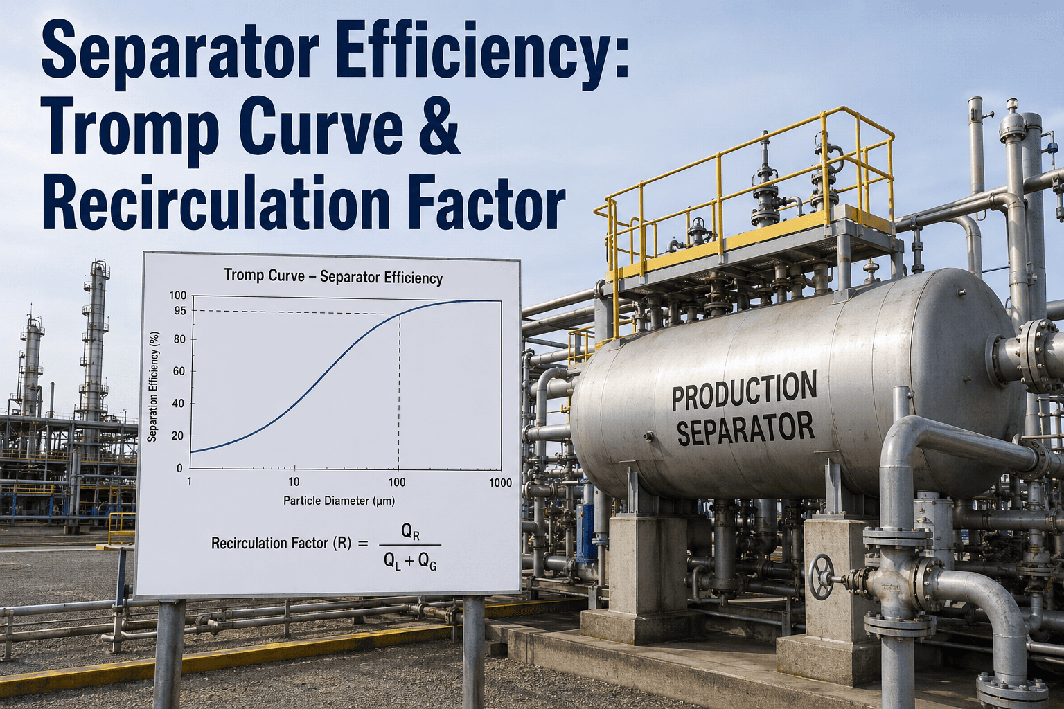
Separator technology didn't improve gradually — it jumped in distinct generations, each solving a specific limitation of the one before it. Static separators offered no active control over the cut point. Second-generation designs added mechanical rotation but still allowed significant bypass — fine material escaping into the coarse reject stream and back into the mill for no reason. Third-generation separators, introduced with external ventilation and a rotor cage design, deliver a materially sharper Tromp curve — the technical term for how cleanly a separator distinguishes fine from coarse particles at the cut size.
| Separator Type | Separation Efficiency | Bypass Behavior | Control Method |
|---|---|---|---|
| First-Generation (Static) | Low, fixed | High, uncontrolled | None — fixed geometry |
| Second-Generation (Mechanical) | Moderate | Moderate | Basic rotor speed adjustment |
| Third-Generation (High-Efficiency) | 80–90%+ | Low, minimized | Rotor speed, airflow, guide vane angle |
Rotor Speed, Airflow, and Guide Vane Angle — the Controls That Set Your Cut Point
Bypass and Circulating Load — the Two Numbers That Tell You the Separator Is Losing
Bypass measures the fraction of already-fine material that escapes classification and rejoins the coarse stream headed back into the mill — the lower the bypass, the more efficient the separation. A rising bypass percentage is the earliest, clearest signal that something in the separator has drifted out of design condition, whether that's airflow restriction, rotor wear, or guide vane misalignment.
Circulating load — the ratio of material recirculated through the mill relative to fresh feed — moves in the same direction as bypass for a reason: every fine particle that bypasses classification adds to the load the mill has to process again. A circulating load climbing from a healthy range toward 280% or higher, without a corresponding change in product fineness targets, is a mechanical or control problem, not a process one, and it is directly costing kilowatt-hours per tonne.
Most Plants Cannot Answer "What Is Our Separator Actually Costing Us Right Now?" Without a 48-Hour Test
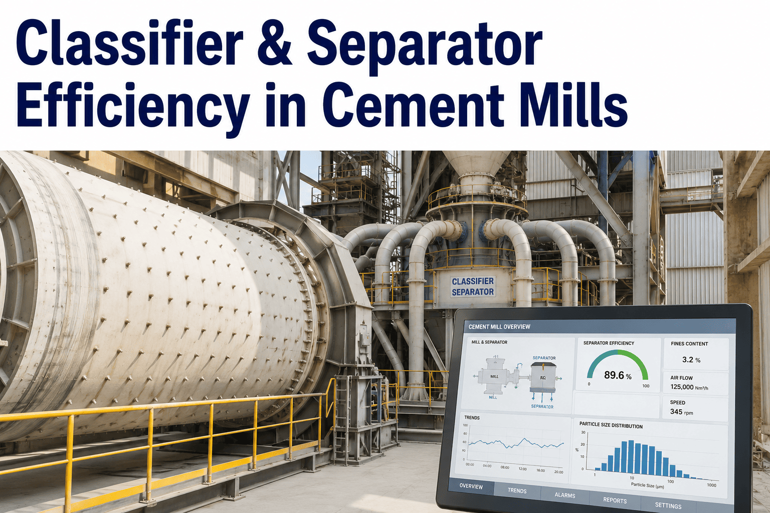
Continuous tracking of circulating load, bypass fraction, rotor speed versus optimum, and fan airflow — updated from your existing mill data — turns that question into a number you can see any time, not just during a scheduled performance test.
What Separator Drift Actually Costs in Kilowatt-Hours Per Tonne
Separator Tuning Matters Differently on a Vertical Roller Mill Than on a Ball Mill Circuit
A vertical roller mill combines grinding and classification in a single unit using material-on-material compression, which already delivers meaningfully lower specific energy consumption than a traditional ball mill. That efficiency advantage is not automatic — it depends on the internal classifier keeping pace with the mill's compression grinding rate. A VRM separator that drifts out of tune erodes the mill's inherent efficiency advantage faster than a comparable drift would on a ball mill circuit with an external separator, because the two stages are more tightly coupled.
On a ball mill circuit with an external high-efficiency separator, the classifier and the mill are more independently tunable — which is both an advantage and a risk. It's easier to isolate and correct a separator problem without touching mill operation, but it's also easier for separator drift to go unnoticed for longer, since the mill keeps grinding at a stable rate even as the separator's cut point quietly degrades.
Before Tuning Setpoints, Check What Airflow and Rotor Wear Are Actually Doing
Control tuning cannot fix a mechanical problem. A separator fan inlet duct partially blocked by accumulated material buildup reduces airflow velocity below design — no amount of rotor speed adjustment recovers the classification sharpness lost to restricted airflow. Rotor blade wear has the same effect from a different direction: worn blades change the centrifugal force profile inside the rotor cage, softening the sharp cut a fresh rotor delivers.
The sequence matters. Restoring mechanical condition first — cleaning ductwork, replacing worn rotor blades, recalibrating guide vane angles to design specification — recovers a meaningful share of lost efficiency before any control optimization even begins. Only after the mechanical baseline is confirmed does adjusting rotor speed and airflow setpoints against real-time clinker grindability data deliver the additional, sustained gain.
The Recurring Checks That Keep a High-Efficiency Separator at Design Performance
Separator efficiency degrades gradually, which is exactly why it goes unnoticed until a quarterly energy report shows an unexplained rise in specific power consumption. Regular performance audits that check for wear, air leakage from false-air ingress, and drift from design setpoints catch degradation while it's still a minor correction rather than a mechanical overhaul. False air entering through poor seals around airlocks is a particularly common and easily missed source of classification disruption — it dilutes the controlled airflow the classifier depends on for a clean cut.
Continuous monitoring of rotor speed, fan power draw, and pressure drop across the classifier — cross-referenced against production rate and clinker grindability — turns separator maintenance from a reactive response to complaints about fineness into a scheduled, data-driven program that keeps the mill circuit running near its productivity ceiling.
Common Separator and Classifier Questions From Cement Mill Operators
Turn Circulating Load and Bypass Into Numbers You Watch Daily, Not Numbers You Discover in a Quarterly Review
Continuous separator monitoring connects to your existing DCS data and surfaces the mechanical and control issues costing kilowatt-hours per tonne — before they show up as a productivity shortfall.