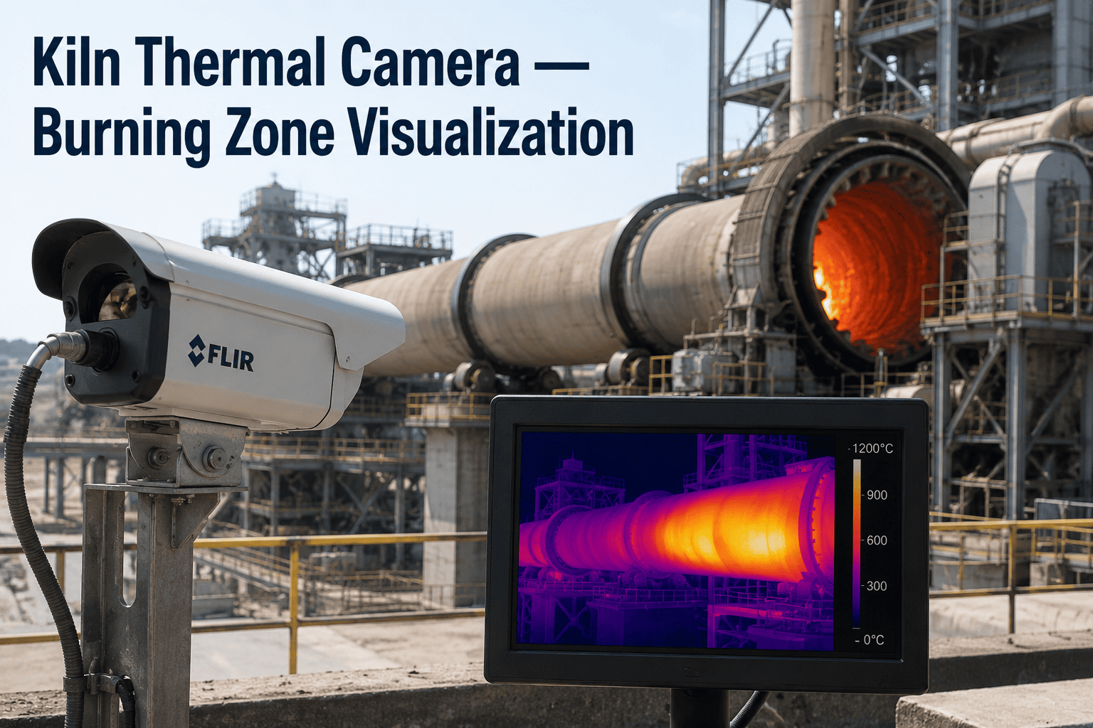
Inside a rotary kiln burning zone, flame temperatures reach roughly 2,000°C and the material bed itself runs near 1,450°C — hot enough to destroy almost any imaging sensor placed directly in the line of sight. For decades, that meant operators judged burning zone health the way their predecessors did: peering through a sight glass, reading flame color by eye, and relying on the shift's most experienced set of eyes to catch a flame shape change before it became a coating failure. A specialized thermal camera changes that by giving the control room a continuous, quantified view of exactly what the flame, coating, and material bed are doing — and AI-driven video analysis turns that feed into an early warning system instead of just a picture on a monitor. Book a free burning zone camera assessment for your kiln.
Quick Answer
A specialized high-temperature thermal camera installed at the kiln hood or burner pipe provides continuous visual and thermal imaging of the burning zone, tracking flame shape, coating condition, material movement, and burner alignment. AI-driven analysis of that video feed quantifies changes an operator's eye would miss, catching coating degradation and burner drift hours to days before they affect clinker quality or fuel consumption.
See What Your Burning Zone Camera Feed Is Actually Telling You
iFactory analyzes your existing burning zone camera video in real time — flame shape, coating condition, and material movement quantified continuously, not eyeballed on a monitor.
What a Thermal Camera Actually Sees Inside a 1,450°C Kiln
Standard cameras fail instantly in a burning zone environment — the heat destroys the sensor, dust cakes the lens, and the flame itself blinds conventional imaging. Purpose-built kiln cameras solve this with three design choices working together.
1
Short-Wave Infrared Sensing Penetrates Flame and Dust
SWIR sensors operating in the 0.8 to 1.1 micron wavelength range see through the bright combustion zone and airborne dust that would blind a standard visible-light camera, resolving detail that would otherwise be washed out by the flame itself.
2
Dual-Spectrum Imaging Adds Visual Context to Thermal Data
Combining a visible-light image with the thermal channel gives operators both a recognizable picture of flame shape and clinker movement and the quantified temperature data needed to track trends numerically rather than by impression.
3
Water and Air Cooling With Auto-Retraction Protect the Hardware
The camera housing is actively cooled and mounted on a retraction mechanism that automatically withdraws the lens from the kiln hood if cooling fails or power is lost, protecting both the equipment and any technician nearby.
Four Things AI-Driven Video Analysis Tracks Continuously
A single burning zone camera feed contains far more usable information than most control rooms currently extract from it. Instead of one operator glancing at a monitor during rounds, continuous AI analysis pulls four distinct signals out of the same video stream, every frame, on every shift.
01
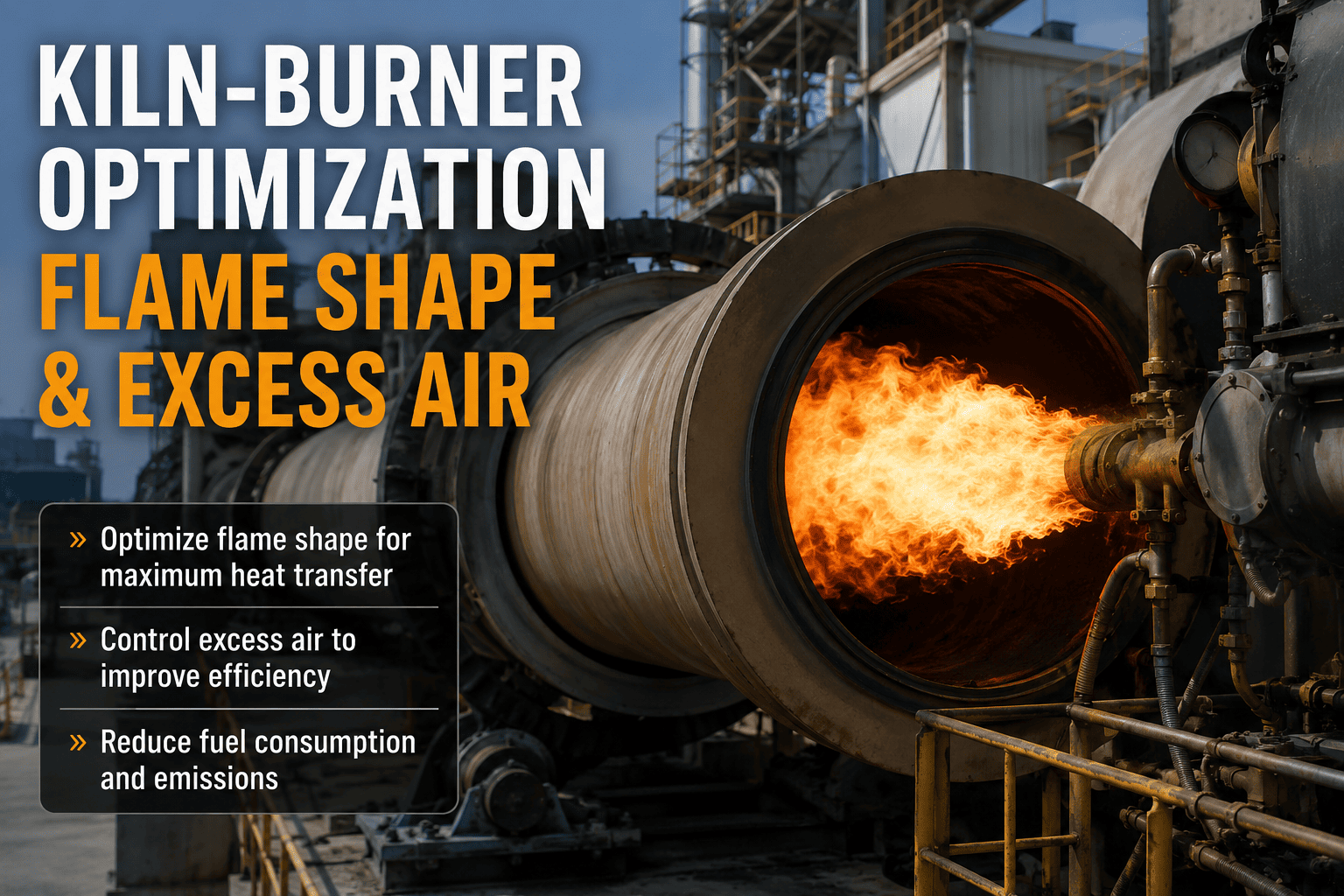
Flame Shape and Stability
Flame length, width, and black root length are measured on every frame rather than judged by eye. A flame that shortens, widens, or develops an irregular root shape signals a burner setting drift, fuel quality change, or air flow imbalance well before it shows up in clinker quality.
02
Coating Condition in the Burning Zone
The protective clinker coating that shields refractory brick is visible in the thermal channel as a distinct temperature signature. AI tracking flags thinning coating sections before they progress to bare refractory exposure and accelerated brick wear.
03
Material Bed and Clinker Movement
Because the kiln rotates continuously, clinker collects on one side of the bed. Tracking how the material moves and falls reveals bed depth changes, filling irregularities, and transition zone behavior that a single-point sensor cannot capture.
04
Burner Tip and Nose Ring Condition
The camera view also captures early buildup on the burner tip, sometimes called rhino horn formation, along with wear patterns on the nose ring segments — both mechanical issues that develop slowly and are easy to miss without a continuous view.
Turn Your Burning Zone Camera Into a Quantified Early Warning System
Most plants already have a burning zone camera feeding a monitor in the control room. iFactory adds the analysis layer that measures flame shape, coating condition, and material movement on every frame and flags the trend before it becomes a problem.
Reading the Flame: What Shape Changes Actually Mean
Flame shape is one of the fastest-changing signals in the burning zone, and it is also one of the most informative once the change is quantified rather than guessed at. Each shape pattern below points toward a distinct root cause, which is why measuring length, width, and root shape separately matters more than watching for a single generic "flame looks off" impression.
| Observed Change |
Likely Cause |
Typical Corrective Action |
| Flame shortens and narrows |
Primary air excess or fuel feed drop |
Check fuel feed rate and rebalance primary air |
| Flame lengthens with a longer black root |
Incomplete combustion or fuel quality shift |
Verify fuel calorific value and burner alignment |
| Flame becomes asymmetric or wanders |
Burner tip wear or misalignment |
Inspect burner tip for rhino horn buildup or wear |
| Flame widens with reduced definition |
Secondary air imbalance |
Adjust cooler grate and secondary air damper settings |
Camera Installation and Calibration Requirements
A burning zone camera only delivers reliable analysis if it is installed, cooled, and calibrated correctly from the start. These four requirements cover the checks worth confirming before treating the feed as a trustworthy monitoring source.
1
Mount at the kiln hood or burner pipe, opposite the material fallBecause the kiln rotates continuously and clinker collects on one side of the bed, mounting the camera under the burner toward the opposite side gives the clearest sightline onto both the flame and the falling clinker.
2
Confirm active cooling capacity matches your kiln's thermal profileWater and air cooling capacity should be sized for your specific burning zone temperature, with margin for upset conditions, since undersized cooling is the most common cause of premature camera failure.
3
Verify auto-retraction triggers on cooling or power lossThe retraction mechanism should be tested during commissioning to confirm it withdraws the lens automatically the moment cooling water flow or power is interrupted, protecting the sensor and anyone working nearby.
4
Schedule regular calibration against a blackbody referenceMonthly calibration against a blackbody reference standard is typical for kiln applications, with more frequent checks warranted in high-dust environments where lens fouling can drift the thermal reading over time.
Our Numbers
2,000°C
Typical Flame Temperature Monitored
3–5%
Fuel Consumption Increase From Poor Flame Shape
4
Process Signals Tracked From One Camera Feed
Hours–Days
Earlier Detection of Coating and Burner Issues
Monthly
Recommended Blackbody Calibration Interval
Zero
New Sight-Glass Manual Checks Required
We already had a burning zone camera — it had been feeding a monitor in the control room for years, and operators glanced at it during rounds. What we didn't have was anyone measuring what it showed. Once iFactory started quantifying flame shape and coating condition from that same feed, we caught a coating thin spot developing over about a week that would previously have gone unnoticed until it showed up as a shell hot spot. We adjusted burner alignment and avoided what would have been an unplanned reline.
Kiln Reliability Lead
5,000 TPD Cement Line — Southeast Asia
Frequently Asked Questions
QDo we need to install a new camera, or can iFactory analyze the feed from our existing one?
Most plants already have a burning zone camera installed, whether a dedicated thermal imaging system or a combined visible and thermal unit, and iFactory typically connects to that existing video feed rather than requiring new hardware. The pre-deployment assessment reviews your current camera's resolution, frame rate, and mounting position to confirm it provides enough detail for reliable flame shape and coating analysis, and identifies any gaps before committing to a full rollout.
Book a camera feed assessment for your kiln.
QHow does AI video analysis catch problems that an experienced operator watching the same feed would miss?
An operator watching a burning zone monitor is making a qualitative judgment in real time, often while managing several other console tasks at once, and subtle gradual changes are genuinely difficult for the human eye to track day over day. AI analysis measures flame length, width, and root shape numerically on every frame and compares the trend against the kiln's own recent baseline, which surfaces slow drifts — a flame narrowing by a small percentage over two weeks, for example — long before they would register as a noticeable visual change to someone glancing at the screen during a round.
QCan the camera and AI analysis distinguish between a genuine coating problem and normal thermal cycling?
Yes. Burning zone coating naturally fluctuates somewhat with normal production cycling, raw mix chemistry shifts, and planned kiln speed changes, and treating every fluctuation as an alarm would create the same alert fatigue that undermines fixed-threshold monitoring systems. The analysis is built around trend direction over days rather than any single frame, distinguishing a coating section that is genuinely thinning progressively from one that is simply cycling within its normal range for that operating condition.
QHow does burning zone camera monitoring relate to shell scanners and pyrometers we may already have?
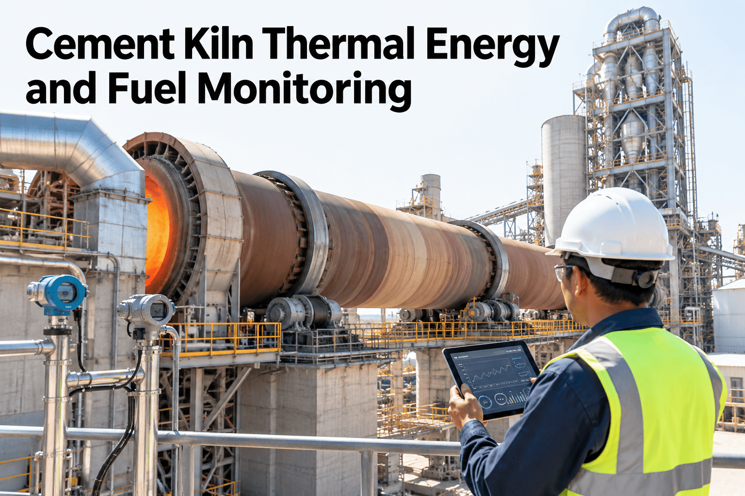
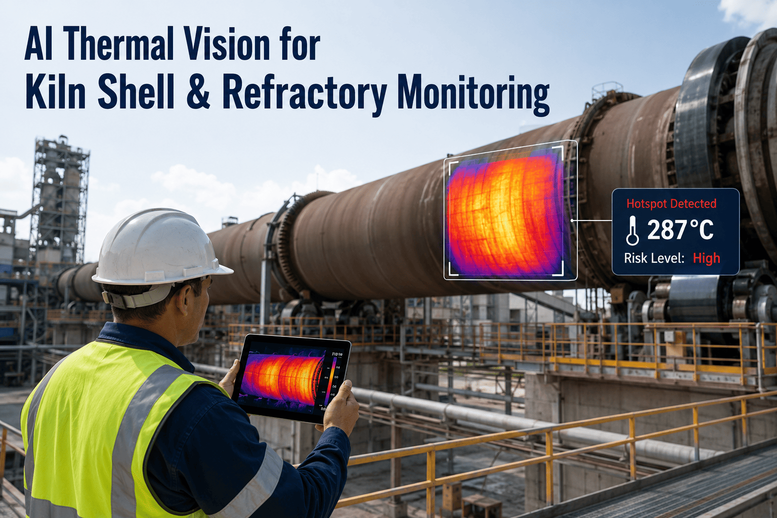
Each instrument protects a different part of the kiln system and none of them fully substitutes for the others. A pyrometer reads flame and clinker bed temperature to protect combustion efficiency, a shell scanner reads the outer steel surface to protect refractory life, and the burning zone camera provides the visual and thermal picture of what is actually happening inside the kiln at the material and flame level. Combining all three into one connected view gives a far more complete picture than any single instrument alone.
QWhat causes a burning zone camera to fail prematurely, and how is that avoided?
Undersized cooling capacity relative to the kiln's actual thermal profile is the most common cause of premature failure, followed by lens fouling in high-dust environments that goes unaddressed between calibration checks. Confirming cooling capacity is matched to your specific burning zone conditions during installation, testing the auto-retraction trigger at commissioning, and following a calibration schedule appropriate to your dust environment addresses the majority of premature failures plants experience.
Talk to an expert about cooling and calibration requirements for your kiln.
Quantify What Your Burning Zone Camera Has Been Showing You All Along
iFactory turns your existing burning zone camera feed into continuous, quantified tracking of flame shape, coating condition, material movement, and burner health — catching issues hours to days before they show up in clinker quality.
Flame Shape Tracking
Coating Condition Analysis
Material Movement Monitoring
Burner & Nose Ring Wear