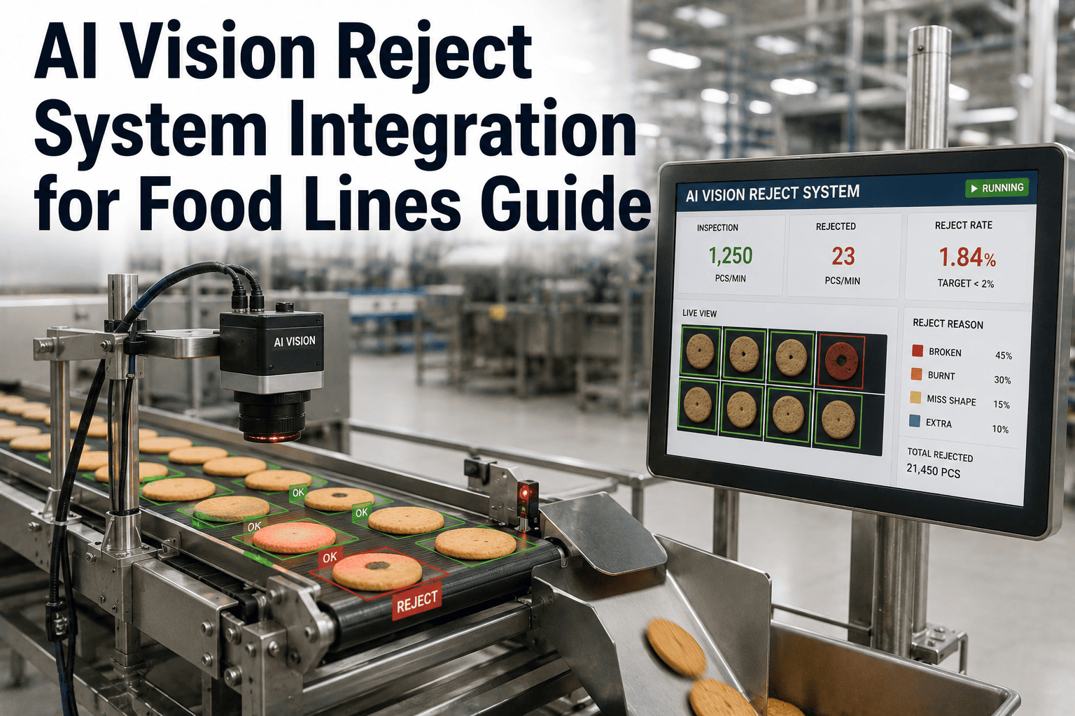
An AI vision model that correctly identifies a defective unit is only half the job — if that decision doesn't translate into a physical reject action within the right window of time, the flagged product sails right past the mechanism meant to pull it, and you're left with a system that detects problems perfectly on a dashboard while doing nothing to stop them reaching a case. Wiring vision decisions to physical reject hardware is where most integration projects actually get hard, because timing, air pressure, and mechanical response all have to line up with millisecond precision. If your team is scoping this integration, book a demo and we'll walk through the reject architecture for your specific line.
Integration Engineering · Food Production Lines
Wiring AI Vision Decisions to Physical Reject Systems on Food Lines
Air blast, arm sweep, and gate diverter integration patterns, the timing math behind each, and the validation steps that confirm a flagged unit actually leaves the line before it reaches packaging.
Why This Step Gets Underestimated
Detection Without Action Isn't Inspection, It's Reporting
Plenty of vision projects stall out at the point of accurate detection and treat the reject mechanism as an afterthought, assuming any actuator with an on-off signal will do. In practice, the gap between a camera flagging a defect and a mechanism physically removing that unit is where the entire value of the system either gets realized or quietly lost. A model with excellent accuracy paired with a poorly timed reject action still lets defective product through, and worse, it can create false confidence, since the dashboard shows the defect was "caught" even though it physically wasn't removed.
Latency Stack-Up
Camera processing time, network transmission, and PLC scan cycle all add delay between detection and action, and each one has to be measured, not assumed.
Line Speed Variability
A reject window calculated at nominal line speed can fail during speed-up periods or after a jam recovery when the line temporarily runs faster to catch up.
Mechanism Mismatch
Choosing an actuator that's too slow, too weak, or poorly positioned for the product weight and line speed undermines even a perfectly timed trigger signal.
Three Common Reject Mechanisms
Choosing the Right Reject Hardware for Your Product
Best for Light, Fast Product
Air Blast Reject
A precisely timed burst of compressed air knocks the flagged unit off the line, ideal for lightweight items on fast-moving conveyors where a mechanical arm would introduce too much delay or physical disruption.
Best for Mid-Weight Product
Arm Sweep Reject
A pneumatic or servo-driven arm physically sweeps the unit off the conveyor into a reject bin, offering more force and control than air alone for heavier or less aerodynamic products.
Best for High-Volume Sorting
Gate Diverter Reject
A pivoting gate redirects the flagged unit onto a separate path entirely, commonly used where product needs to be routed for rework or secondary inspection rather than dropped straight into scrap.
The Numbers That Matter
Timing and Latency Budget Across the Detection-to-Reject Chain
| Stage | Typical Latency | What Affects It |
|---|---|---|
| Image capture and inference | 5 to 40 milliseconds | Model complexity, camera frame rate, processing hardware |
| Decision transmission to PLC | 1 to 10 milliseconds | Network protocol, message queue depth |
| PLC scan cycle to actuator | 5 to 20 milliseconds | PLC scan time, program complexity |
| Physical actuator response | 10 to 100 milliseconds | Mechanism type, air pressure, mechanical wear |
| Product travel to reject point | Depends on line speed and distance | Encoder accuracy, conveyor speed consistency |
The reject point must sit far enough downstream of the camera that the total of every stage above still fits comfortably within the product's travel time, with margin for line speed variation.
Get the Timing Right the First Time
iFactory Engineers Validate Your Reject Timing Before Go-Live
We measure your actual latency stack across camera, network, and PLC, and confirm reject mechanism placement against your real line speed range, not just nominal spec sheet numbers.
Implementation Path
How a Reject Integration Project Actually Gets Built
Phase 1
Measure the Existing Line
Document actual line speed range, encoder resolution, camera-to-reject-point distance, and existing PLC scan cycle before specifying any hardware or writing any logic.
Phase 2
Select and Position the Mechanism
Choose air blast, arm sweep, or gate diverter based on product weight and shape, then position it at a distance that provides adequate margin above the calculated total latency.
Phase 3
Build the Trigger Logic
Program the PLC to track flagged units by encoder position rather than time alone, so the reject fires based on physical location regardless of momentary speed changes.
Phase 4
Validate at Full Speed Range
Test reject accuracy at minimum, nominal, and maximum line speed, including immediately after a speed-up or jam recovery scenario, before considering the integration complete.
Before Go-Live
A Validation Checklist Most Teams Skip Too Quickly
Confirm Reject Accuracy Across the Full Speed Range
Run test units at slowest and fastest observed line speeds, not just the nominal average speed used during initial setup.
Test Consecutive Reject Scenarios
Verify the mechanism can cycle fast enough to reject two flagged units in close succession without missing the second one.
Verify Behavior During Line Stoppage and Restart
Confirm the encoder-based tracking correctly resumes after a stop, rather than assuming units continued moving during the pause.
Log Every Reject Event With Image Reference
Tie each reject action back to the triggering image and timestamp, so any disputed reject can be reviewed and the model tuned accordingly.
The single most common mistake I see is timing the reject window against average line speed and never testing it during a jam recovery, which is exactly when the line often runs faster to make up time and exactly when the reject window gets tightest. If your validation testing doesn't include that scenario, you don't actually know your reject system works under real conditions. Test at the edges, not just the middle, and use position-based triggering rather than time-based wherever the PLC supports it.
Devrim Osei-Bergström
Controls Integration Engineer · 18 years building reject and sortation logic for food and beverage lines
Integration Questions
Reject System Integration — Frequently Asked
How far downstream should the reject mechanism sit from the camera?
The distance needs to cover the total latency across camera processing, network transmission, PLC scan cycle, and actuator response time, converted into product travel distance at your maximum expected line speed, plus a reasonable safety margin. There's no universal number here, since it depends entirely on your specific hardware stack and line speed range, which is why measuring actual latency on your line matters more than using a generic spec sheet estimate from equipment vendors.
Should reject timing be based on elapsed time or encoder position?
Encoder position tracking is strongly preferred over time-based triggering, because it accounts for line speed variation automatically. A time-based trigger calculated for nominal speed will fire too early if the line briefly speeds up, missing the flagged unit entirely. Position-based tracking follows the actual physical location of the flagged unit regardless of momentary speed changes, which makes it far more reliable across real-world operating conditions including jam recovery periods.
What happens if the reject mechanism fails to fire on a flagged unit?
A well-designed system logs every trigger command sent to the actuator alongside a downstream confirmation, whether from a sensor at the reject bin or a secondary check, so a missed reject is flagged rather than silently lost. Some plants add a secondary verification camera after the reject point specifically to confirm flagged units actually left the line. Contact our support team to discuss verification options for your setup.
Can one reject mechanism handle multiple defect types from the same vision system?
Yes, in most cases a single reject mechanism can handle any defect type the vision system flags, since the mechanism only needs a trigger signal, not knowledge of why the unit was flagged. Some plants do use separate reject points for different defect categories when they want to route product differently, such as sending fill-level issues to rework while sending contamination flags directly to scrap.
How often should reject timing be re-validated after initial setup?
Re-validate any time line speed settings change, after mechanical maintenance on the reject actuator, or after a product changeover that alters unit weight or shape significantly enough to affect actuator force requirements. Many plants build a quarterly validation check into their preventive maintenance schedule as a routine confirmation rather than waiting for a problem to surface. Book a demo to see how validation is typically scheduled.
Close the Loop on Detection
Make Sure Every Flagged Defect Actually Leaves the Line
iFactory's integration team measures your real latency stack and validates reject timing across your full line speed range before go-live, not just on paper.