Cut open a poorly brazed refrigerant joint months after installation and the evidence is unambiguous: black carbon deposits lining the inside of the pipe, the unmistakable signature of oxygen that was never displaced during brazing. On one documented inspection, every single joint sampled showed the same contamination — an inadequate nitrogen purge that would not have caused a single failure at commissioning, but was already circulating debris toward every compressor and expansion valve in the system. iFactory's installation verification platform exists to catch that gap during the brazing itself, not months later when a strainer clogs or a compressor fails.
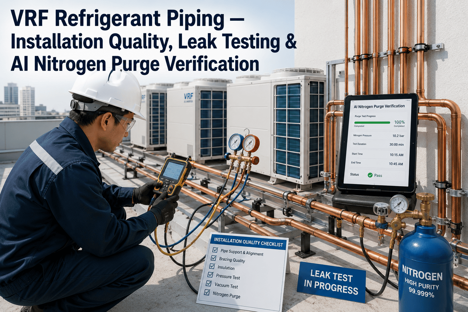
VRF Refrigerant Piping: Installation Quality, Leak Testing & AI Nitrogen Purge Verification
A VRF system's long-term reliability is decided during installation, not during operation. This guide covers the brazing, nitrogen purge, and pressure testing standards that separate a system that runs clean for fifteen years from one that fails within its first two.
Why Installation Quality Determines a VRF System's Entire Lifespan
A VRF system's refrigerant piping network is sealed and, in most installations, largely inaccessible once commissioned. Whatever contamination, moisture, or oxidation enters the system during installation stays in the system — there is no equivalent of an oil filter change to periodically clean out debris that shouldn't have been there in the first place. This makes VRF piping installation fundamentally different from most other mechanical work: a shortcut taken during brazing doesn't show up as a defect at handover. It shows up eighteen months later as a clogged strainer, a restricted expansion valve, or a compressor that failed carrying contaminated oil.
The foundational principle governing refrigerant piping quality is commonly summarized as Dry, Clean, and Tight — DCT. Refrigerants and moisture are chemically incompatible; moisture combines with refrigerant and oil to form acids that attack internal components from the inside. Contamination from oxidation during brazing circulates as particulate through fine-mesh strainers and precision components designed for a clean system, not a system carrying scale. And a joint that isn't mechanically tight, whatever its other qualities, is a leak path waiting for enough thermal cycling to open it. Every installation quality practice covered below exists to satisfy one of these three requirements.
What makes VRF systems specifically more sensitive to installation shortcuts than simpler split-system air conditioning is the sheer complexity of the piping network involved. A single outdoor condensing unit typically feeds a branching network of refnet joints and piping runs to dozens of indoor units, often across multiple floors of a building, with electronic expansion valves at each indoor unit metering refrigerant flow with a precision that leaves very little tolerance for circulating debris. A contamination source at any single joint in that network has the potential to affect every downstream indoor unit sharing the same refrigerant circuit, not just the branch nearest where the contamination originated. This is fundamentally different from a residential split system, where a compromised installation typically affects one indoor unit in isolation.
Verify Every Braze Was Purged Correctly, Not Just Assumed
iFactory documents nitrogen flow, pressure, and duration against every brazed joint, turning an assumption into a verified installation record.
Why Nitrogen Purge Is Non-Negotiable During Brazing
Brazing copper refrigerant piping in open air, without displacing the oxygen inside the pipe, produces internal oxidation — a black scale that forms on the interior pipe wall exactly where it's invisible until the joint is cut open. This problem existed with older refrigerants but became measurably worse with the shift from HCFC refrigerants using mineral oil to modern HFC refrigerants using polyolester oils. POE oils have a solvent effect that actively scrubs oxide and loose scale from copper tube walls, meaning contamination that formed during a rushed brazing job doesn't just sit inertly in one spot — it circulates through the entire system, reaching strainers, electronic expansion valves, and compressors.
Dry nitrogen is introduced into the piping — typically through a Schrader valve at the outdoor condensing unit or another convenient access point — at a low flow rate and pressure, commonly cited at 2 to 3 CFH and 1 to 2 PSI. The nitrogen must flow continuously throughout the entire brazing operation, not just before it starts, and critically must continue flowing until the pipe has fully cooled. Stopping the purge as soon as the flame is removed, before the joint cools, allows residual oxygen to re-enter the still-hot pipe and oxidize exactly the area that was just protected. Flux should never be used on copper-to-copper refrigerant brazing — a chlorine-based flux can corrode the pipe, while fluorine-based flux degrades refrigerant oil, meaning flux misuse doesn't just fail to help, it actively creates a second contamination source alongside any oxidation the purge was meant to prevent.
What a Properly Purged Joint Looks Like — and What a Bad One Looks Like
The difference between an adequately and inadequately purged joint is visually unambiguous when inspected, which is exactly why destructive testing on sample joints has become a valuable quality verification technique on larger installations. A properly brazed joint with a continuous nitrogen purge appears clean and smooth on the interior, with no discoloration, debris, or carbon residue. A joint brazed with an inadequate or interrupted purge shows visible carbon deposits and discoloration, and in more severe cases, pitting — small pockets or voids in the copper wall that create thin spots capable of failing under normal operating pressure and thermal cycling over time.
Carbon particles formed during inadequately purged brazing don't stay at the joint where they formed. They circulate through the refrigerant loop and accumulate wherever the system design concentrates flow restriction — fine mesh strainers, the narrow orifices of electronic expansion valves, and ultimately the close-tolerance moving components inside a compressor. A compressor failure caused by circulating debris is disruptive in a way a single leaking joint is not: when a compressor fails, every indoor unit connected to that outdoor unit typically loses both heating and cooling capability simultaneously, not just the branch nearest the original contamination.
Catch Purge Quality Issues at Installation, Not During a Compressor Failure
iFactory logs purge flow and duration in real time against each brazed connection, flagging incomplete or interrupted purges before insulation covers the joint.
Pressure Testing: Verifying the System Is Actually Tight
Brazing quality and pressure testing are related but separate verification steps — a joint can be adequately purged and still fail a pressure test if it wasn't mechanically sound, and pressure testing is the step that catches that failure before the system is charged with refrigerant and put into service. Testing should always occur before piping insulation is installed, since insulated joints cannot be visually inspected for leaks during the test itself.
Test pressures and durations vary by manufacturer and should always be confirmed against the specific system's installation documentation, but a representative staged protocol holds 150 PSI for 3 minutes, then increases to 325 PSI held for 5 minutes, and finally increases to 550 PSI or higher, held constant for a full 24 hours. A steady pressure reading across that extended final hold — with no measurable decay — is the verification that the system is leak-free. Dry nitrogen is the testing medium of choice specifically because it avoids introducing moisture into the system during a step that happens before the final vacuum and dehydration process, and because it is far safer and less expensive than testing with refrigerant itself.
Once the pressure test confirms mechanical tightness, the system still needs to be evacuated to remove residual air and moisture before refrigerant charging — commonly pulling down to 500 microns or lower and holding to confirm the vacuum doesn't rise, which would indicate residual moisture still evaporating inside the system. Breaking a vacuum should always be done with nitrogen, never by opening the system to ambient air, since doing so reintroduces exactly the moisture and oxygen the entire DCT process was designed to keep out.
Installation Quality Checkpoints and What Each One Verifies
| Checkpoint | What It Verifies | Common Failure Mode | Verification Method |
|---|---|---|---|
| Pipe material & sizing | Correct copper grade and diameter per manufacturer spec | Wrong wall thickness or diameter for run length | Documentation review |
| Nitrogen purge during brazing | No internal oxidation forming during the joint | Purge stopped before pipe fully cooled | Real-time flow/duration logging |
| Joint visual/destructive inspection | Clean, smooth interior with no carbon or pitting | Discoloration indicating inadequate purge | Sample joint cross-section |
| Staged pressure test | Mechanical tightness of every joint and connection | Slow pressure decay over 24-hour hold | Documented pressure log |
| Vacuum dehydration | Residual moisture removed before charging | Micron level rises after pump shutoff | Decay test verification |
| Post-charge leak verification | No leaks introduced during charging or commissioning | Flare connection loosened during final assembly | Electronic or acoustic leak scan |
AI-Assisted Verification: Closing the Documentation Gap
The technical standards for nitrogen purge and pressure testing have been well established for decades. What has historically been unreliable is documentation — proving, after the fact, that a specific joint was actually purged for the correct duration at the correct flow rate, rather than relying on a technician's memory or a generic sign-off sheet completed after the fact. This gap matters enormously when a failure occurs months or years later and the question becomes whether the original installation met specification.
Modern verification tools layer several capabilities on top of the underlying physical process rather than replacing it: automated logging of nitrogen flow rate and pressure against timestamped brazing events, image or thermal capture of joints before insulation for a permanent visual record, and anomaly detection that flags a purge duration inconsistent with the pipe size and cooling time required. On the leak-detection side, acoustic imaging and infrared sensing can identify a refrigerant leak's ultrasonic signature or concentration pattern well before a technician using a handheld sniffer would locate it manually — particularly valuable in the congested piping runs and hard-to-reach mechanical spaces typical of VRF installations. None of this replaces correct brazing and testing technique; it replaces the unverifiable assumption that correct technique was followed with an actual documented record.
Regulatory Context: Why Documentation Increasingly Isn't Optional
Refrigerant leak management carries direct regulatory exposure under EPA Section 608, with mandatory repair thresholds that vary by system type — commercial comfort cooling systems must address leaks at a 10% annual leak rate, industrial process refrigeration at 30%, with civil penalties for non-compliance reaching tens of thousands of dollars per day per violation. New automatic leak detection requirements taking effect for equipment installed from January 2026 onward add a further layer: for systems above defined refrigerant charge thresholds, automatic leak detection must be operational within 30 days of installation, with existing equipment required to comply by January 2027. A poorly installed system that leaks prematurely doesn't just cost more in refrigerant and repairs — it creates a compliance exposure that a well-documented, correctly installed system avoids entirely.
This regulatory shift changes the calculus for how installation documentation gets treated. A quality record that was previously useful mainly for internal troubleshooting or warranty disputes now doubles as evidence in a compliance context — if a system leaks and a regulator or auditor asks how the installation was verified, "the technician followed standard procedure" carries far less weight than a timestamped record of purge flow, pressure test results, and vacuum decay figures tied to that specific system. Facilities managing a portfolio of VRF installations across multiple buildings or sites face this exposure multiplied across every system, which is precisely why documentation infrastructure that scales across an entire portfolio has become as operationally important as the underlying installation technique itself.
Common Mistakes in VRF Piping Installation
Stopping nitrogen flow as soon as the torch is removed. The pipe is still hot and chemically reactive with oxygen for a meaningful period after brazing ends. Purge needs to continue until the joint has fully cooled, not until the visible flame stops.
Using flux on copper-to-copper refrigerant joints. Refrigerant piping brazing generally should not use flux at all — chlorine-based flux corrodes copper, and fluorine-based flux degrades refrigerant oil. Habits carried over from plumbing or other trades that rely on flux don't transfer safely to refrigerant work.
Skipping the pressure test hold time to save schedule. A short pressure hold can look identical to a proper 24-hour hold on a gauge read five minutes in — the entire point of the extended hold is to catch slow leaks that only reveal themselves over time.
Insulating pipes before pressure testing is complete. Once insulation covers a joint, visual leak inspection during testing becomes impossible. Testing has to happen first, in the correct sequence, not retrofitted around a schedule that insulated early for convenience.
Breaking a vacuum with ambient air instead of nitrogen. This single shortcut reintroduces the moisture and oxygen that the entire dry-clean-tight process was designed to exclude, undoing careful work at every prior step in one action.
Installation Quality KPIs to Track
Purge-Verified Joint Rate
Percentage of brazed joints with documented nitrogen flow rate and duration logged against the specific joint, not just a general job-site sign-off.
24-Hour Pressure Test Decay
Pressure loss over the extended hold period as a percentage of starting test pressure. Near-zero decay confirms mechanical tightness across the full piping network.
Post-Commission Leak Events (First Year)
Leaks discovered within the first twelve months of operation. A properly installed system should show effectively zero, since installation-driven leaks typically reveal themselves early under thermal cycling.
Contamination-Related Component Failures
Strainer clogs, EEV restrictions, or compressor failures attributable to circulating debris, tracked against the specific installation crew or job to identify systemic purge quality issues before they scale.
Every VRF failure I've investigated that traced back to installation quality had the same characteristic: it looked completely fine at commissioning. The system charged, ran, and cooled the space on day one. The carbon deposits from an inadequate purge don't announce themselves — they sit quietly in the piping for months while they slowly work their way toward a strainer or an expansion valve. By the time anyone notices a problem, the installation crew is long gone and there's no record of what actually happened during brazing eighteen months earlier. The only real fix is verifying the purge while it's happening, not investigating the failure after the fact.
Frequently Asked Questions
Brazing copper piping in open air allows oxygen inside the pipe to react with the heated metal, forming internal oxidation and carbon scale on the interior wall. Nitrogen, being inert and non-reactive, displaces that oxygen during the brazing process, preventing the scale from forming in the first place. This matters more with modern HFC refrigerants using polyolester oils than it did with older refrigerants, because POE oils have a solvent effect that actively scrubs any oxide that does form off the tube walls and circulates it through the system as debris. Book a demo to see how iFactory documents purge compliance against every brazed joint automatically.
A commonly cited standard for VRF brazing purge is a low flow rate of 2 to 3 CFH at 1 to 2 PSI, introduced through a Schrader valve or other convenient access point and maintained continuously throughout the brazing operation. The goal is a low-volume, low-pressure flow sufficient to displace oxygen without creating turbulence or excess backpressure at the joint. Flow must continue until the pipe has fully cooled after brazing is complete, not just until the torch is removed, since the still-hot metal remains chemically reactive with oxygen during the cooling period. Book a demo to see real-time purge flow and duration verification on your own installations.
A properly purged joint, when cut open for inspection, shows a clean, smooth interior with no discoloration, carbon deposits, or debris. An inadequately purged joint shows visible carbon buildup and discoloration, and in more advanced cases, pitting in the copper wall — small voids that create thin spots capable of failing under normal operating pressure over time. Destructive sample testing on a subset of joints is one way to verify purge quality on a completed installation, though it obviously cannot inspect every joint without damaging the system. This is exactly why real-time documentation during the brazing process itself is more practical at scale than after-the-fact destructive verification. Book a demo to see how iFactory creates a documented quality record without needing to cut open finished joints.
Protocols vary by manufacturer and should always be confirmed against specific installation documentation, but a representative staged approach holds 150 PSI for 3 minutes, increases to 325 PSI held for 5 minutes, and finally increases to 550 PSI or higher held constant for a full 24 hours, with a steady pressure reading across that extended hold confirming the system is leak-free. Testing uses dry nitrogen rather than refrigerant, both for safety and cost reasons, and must be completed before piping insulation is installed, since insulated joints cannot be visually inspected during the test. Book a demo to see how iFactory logs and timestamps every stage of a pressure test automatically.
Under EPA Section 608, systems above defined refrigerant charge thresholds face mandatory leak repair requirements tied to annual leak rate, with comfort cooling systems generally required to address leaks at a 10% annual rate and industrial process refrigeration systems at a higher 30% threshold, backed by civil penalties reaching tens of thousands of dollars per day for non-compliance. New requirements taking effect for equipment installed from January 2026 onward mandate automatic leak detection systems operational within 30 days of installation for qualifying equipment, with existing systems required to comply by January 2027. A correctly installed, well-documented system is far less likely to trigger these thresholds in the first place than one with installation-driven contamination or slow leaks working their way toward failure. Book a demo to see how iFactory ties installation quality documentation to ongoing leak rate compliance tracking.
Give Every Brazed Joint a Verified, Timestamped Quality Record
iFactory documents nitrogen purge, pressure testing, and leak verification against every VRF installation — so quality is proven at the time of work, not assumed and discovered wrong months later.