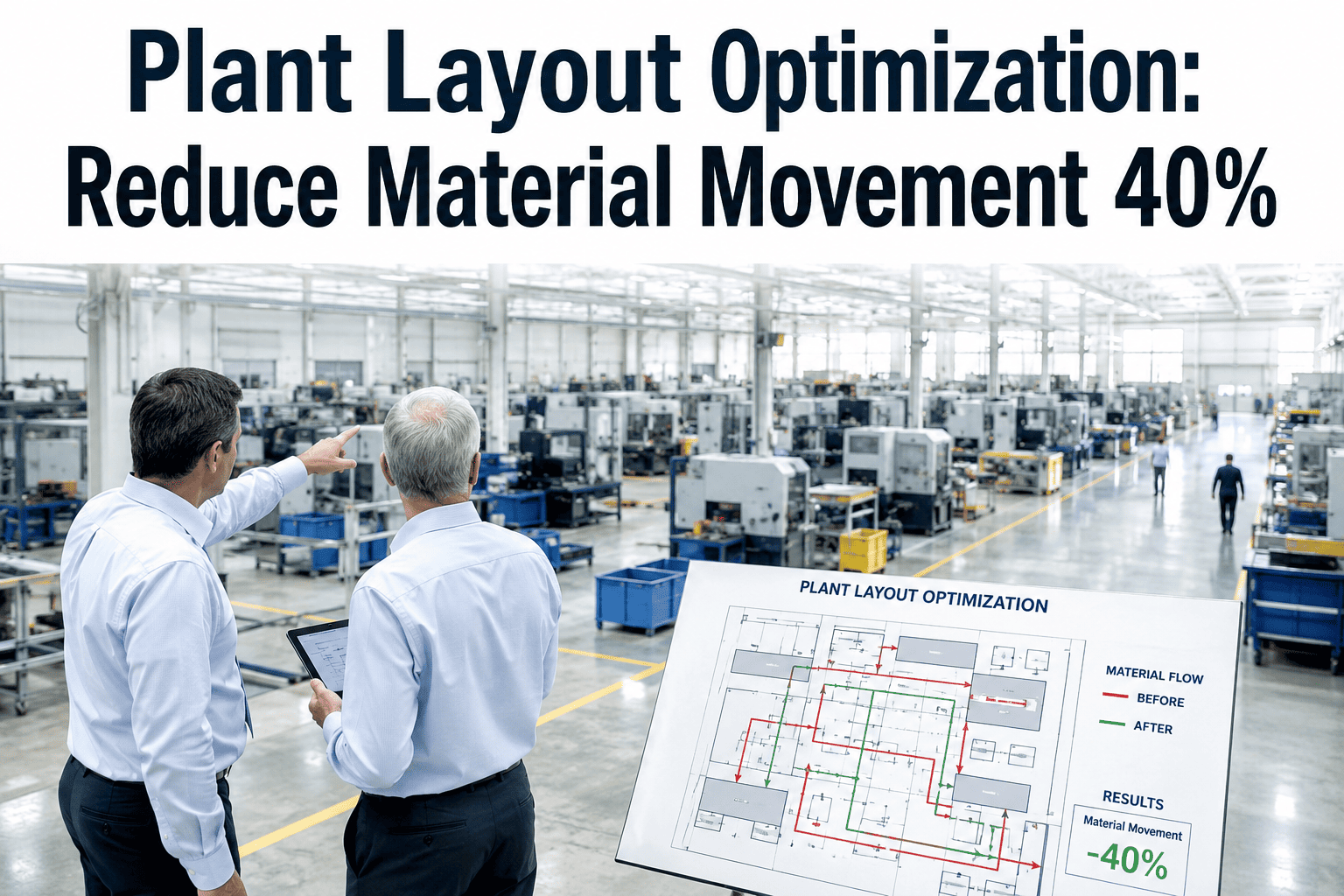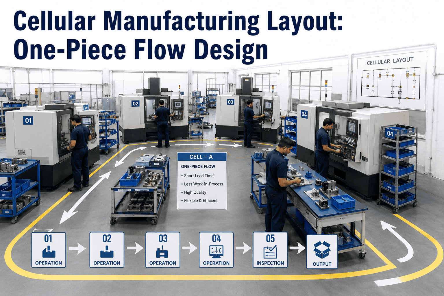
Batch manufacturing trains operators to make a hundred parts, push them into a queue, and then move on to the next operation while those hundred parts sit waiting for their turn at the next station. Cellular manufacturing inverts that entire logic by arranging equipment so that a single part moves from one step to the next with almost no waiting in between, which collapses lead time from days to hours and WIP from thousands of pieces to a handful. The design challenge is not understanding the concept but figuring out which machines go where, which operators walk which path, and how to keep every station balanced to the same takt time without overstaffing the cell, and you can book a demo to see how iFactory maps your current layout and models cell alternatives digitally.
Batch Queue Times Disappear When You Arrange Equipment Around the Part Instead of the Other Way Around
Cellular manufacturing places all required operations for a product family within arm's reach so a single part flows continuously from raw material to finished good without pausing in a WIP queue between stations.
What Actually Changes When You Switch from Departmental Layout to Cellular Layout
The difference between these two layouts is not aesthetic. It is a fundamental shift in how material accumulates, how long it takes to complete an order, and how many hands touch each part before it ships. The visualization below traces the same order of fifty parts through both layout types and measures what happens at each step.
How to Group Products Into Families That Share a Manufacturing Cell
Not every product belongs in a cell, and not every cell should contain every product. The formation process starts by identifying which products share similar routing sequences so they can flow through the same set of equipment arranged in the same order. The most practical tool for this is a Product-Quantity analysis combined with a routing matrix that reveals natural product family clusters.
Three Cell Layout Shapes and When Each One Is the Right Choice
The physical shape of the cell determines how far the operator walks, how many operators the cell can support, and whether material can enter and exit at the same point. There is no universally correct shape, but there is usually a clearly wrong one for any given set of equipment, part size, and operator count. The comparison below maps the strengths and tradeoffs of the three most common configurations.
Single operator managing 4-8 stations. Material enters and exits at the same point, which simplifies material handling and allows one person to walk the interior of the U while parts travel the exterior.
Requires enough floor depth to accommodate the U. Does not work well if equipment is too large to fit in a compact arrangement or if parts are too bulky to pass between close stations.
Long narrow floor spaces, large parts that move on conveyors between stations, or processes that require a linear sequence such as paint lines or heat treatment sequences that cannot bend back on themselves.
Operator walks twice as far as a U-shape for the same number of stations because the return path is the full length of the cell. Separates input and output points, which complicates material handling.
Corner floor spaces, cells that need to integrate with existing equipment that cannot be moved, or product families where a natural break in the routing allows the flow to turn a corner without losing efficiency.
Walking distance is between the U-shape and straight-line. The corner station can become a bottleneck if the operator path is not carefully designed to avoid crossing the material flow path at the bend.
Balancing Every Station to Takt Time Is What Makes One-Piece Flow Actually Work
One-piece flow fails the moment any single station takes longer than takt time because the part cannot move forward and the operator is stuck waiting at that station while downstream stations sit idle. The visualization below shows a cell where the work has been redistributed across stations so that every step completes within the takt window, which is the condition that allows continuous flow to exist.
Mill station took 115 seconds, exceeding takt by 25 seconds. Every part stalled at Mill. Downstream stations starved. One-piece flow was impossible despite the cell being physically arranged correctly.
20 seconds of milling work moved to Drill and Deburr stations that had spare capacity. Mill dropped to 76 seconds. All stations now within takt. One-piece flow operates continuously without stalling at any point.
See Your Product Families Mapped Into Optimized Cell Layouts Digitally
iFactory analyzes your routing data, identifies product families, calculates takt time, and generates cell layout alternatives with operator walking paths and balance charts before you move any equipment.
How to Assign Operators to a Cell Without Overstaffing or Creating Idle Time
The number of operators in a cell is determined by dividing total work content by takt time, but the actual assignment requires mapping which stations each operator walks to and ensuring that the walking path does not cross the material flow path. The visualization below shows a balanced five-operator assignment in a U-shaped cell where each operator handles between 70 and 88 seconds of work per cycle.
Cell Design Decisions That Look Correct on Paper But Fail on the Production Floor
These mistakes appear repeatedly across cell implementation projects because they address the physical arrangement without considering the operational dynamics that emerge once the cell is running at speed. Each one has a visible symptom that operators notice immediately and engineers often misdiagnose as a staffing or training problem rather than a layout problem.
Engineers balance station cycle times to takt but forget to add the 5-8 seconds the operator spends walking between stations. The cell stalls because the loaded operator exceeds takt when walking is included, and the symptom looks like a capacity problem when it is actually a walking distance problem.
A machine is positioned for minimal footprint but the operator has to flip the part 180 degrees to load it, adding 10 seconds of handling time that was not in the original cycle time estimate. Repeated across multiple stations, these small orientation costs accumulate into a balance failure.
The cell is staffed for average volume and cannot scale up when orders spike. When demand increases, the cell cannot add a sixth operator because the walking paths are not designed for it, so the response is to run overtime or split the cell, both of which defeat the purpose of the cellular design.
Product families are defined too broadly and the cell ends up containing equipment that is only used for a few SKUs. The result is a large cell with low utilization on some stations and frequent changeovers that break the one-piece flow rhythm for the high-volume products that should have had a dedicated smaller cell.
Defects are not detected until the final inspection station, which means the cell continues producing bad parts for multiple cycles before anyone notices. In a one-piece flow cell, every station needs a quick pass-fail check so defects are caught immediately at the source rather than accumulating through the entire sequence.
Equipment Arrangement Principles That Determine Whether the Cell Flows or Stalls
The distance between machines, the direction they face, the height of the work surface, and the location of raw material and finished goods bins all affect whether an operator can maintain takt pace or spends their cycle fighting the physical layout. The rules below are derived from hundreds of cell implementations and represent the non-negotiable starting points that experienced cell designers apply before considering any custom arrangement.
Arrange equipment so operators face each other across the cell rather than facing walls. This enables communication, allows cross-training to happen visually, and lets operators hand parts directly to each other rather than placing them on a table or conveyor between stations.
The distance between any two consecutive stations should not exceed the distance an operator can reach without taking a step. If the operator has to walk more than one pace between stations, the walking time becomes a significant portion of the cycle and the cell cannot balance to a short takt time.
All work surfaces in the cell should be at the same height so the operator does not have to adjust their posture when moving between stations. Height variations between stations add fatigue over a shift and create micro-delays that are invisible individually but measurable in aggregate.
Raw material for at least two hours of production should be stored within the cell at the first station, and finished goods should be staged at the last station. Requiring the operator to leave the cell to get material breaks the flow and introduces variability into the cycle time.
Material should always move in one direction through the cell, even if the cell shape curves. If a part has to move backward to reach the next operation, the layout is forcing the operator to either carry the part against the flow or place it in a buffer, both of which break one-piece flow.
Each station should have a visible takt board, a standard work instruction, and a signal mechanism for when the operator needs help. Without visual management at the station level, problems are hidden until they cause the cell to stop, which is the opposite of what a cell design should enable.
Results Reported From Cellular Manufacturing Layout Implementations
The figures below reflect outcomes tracked across manufacturing facilities that converted from departmental batch layouts to cellular one-piece flow layouts, compared against each facility's own baseline measured over comparable production periods before and after the cell implementation. Results vary by industry and product complexity but the directional improvements are consistent.
Questions Manufacturing Engineers Ask About Cellular Layout and One-Piece Flow Design
Design Your Manufacturing Cells Digitally Before Moving a Single Machine
iFactory's platform groups your products into families, calculates takt time, generates cell layout alternatives with walking paths, and simulates one-piece flow performance so you know exactly what to expect before implementation begins.