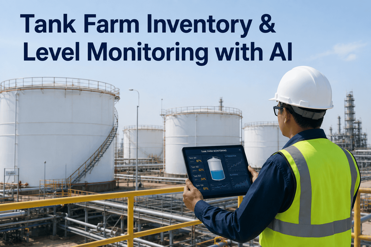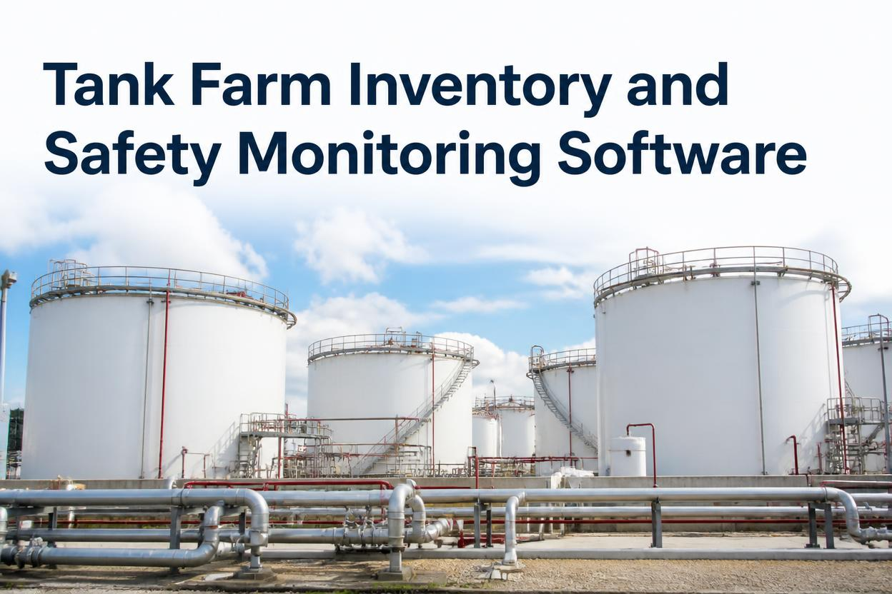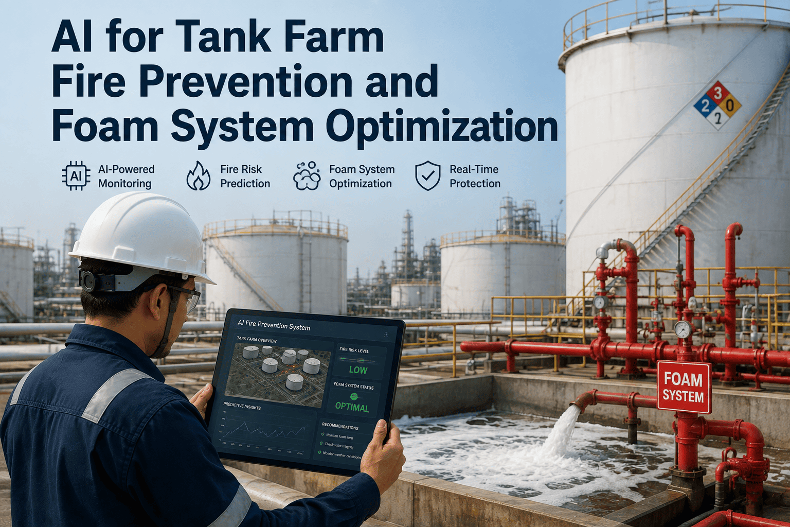
Rim-seal fires are the most common ignition event on floating roof tank farms, and roughly 95% of them trace back to a single, largely invisible trigger — lightning-induced arcing across a seal gap that no operator can see from the ground. A refinery running 50 large floating roof tanks can statistically expect a rim-seal fire about once every ten years, and once flame is visible, the foam system has seconds, not minutes, to respond correctly. Most tank farms still rely on periodic manual rounds to check foam concentrate levels, seal condition, and roof temperature, leaving long gaps where a developing hazard goes completely undetected between checks. AI-based monitoring closes that gap by continuously reading tank surface temperatures, vapor space composition, and foam system readiness in real time, flagging deviations well before they reach ignition conditions. Plant HSE teams who want a system mapped to their exact tank configuration and NFPA 11 protection scheme can book a demo to see how continuous monitoring fits their fire protection plan.
Rim-seal fires do not announce themselves. A seal degrades slowly over years of filling, draining, corrosion, and thermal cycling, and the electrical arc that ignites escaping vapor happens in a fraction of a second during a lightning event that may not even strike the tank directly. Because the failure mode is both slow-building and instantaneous at the point of ignition, manual inspection rounds — even disciplined ones — miss the window where the risk was actually visible in the data. Compounding the problem, a strike does not need to hit the tank at all: research on floating roof tank lightning behavior shows that current flows across the roof-to-shell seal during nearby strikes as well as direct hits, which means the population of tanks exposed to arcing risk during a storm is far larger than the handful that would show visible strike damage afterward. The numbers below explain why tank farms consistently underrate this exposure until an incident forces a re-evaluation of the entire fire protection program.
Not every tank fire behaves the same way, and NFPA 11 does not treat them the same way either. A rim-seal fire, a full liquid surface fire, and a dike or bund fire each demand a different application rate, a different minimum discharge duration, and a different verification that the system is actually capable of delivering it. Confusing the three — or assuming a system sized for one scenario automatically covers another — is one of the most common gaps AI monitoring is used to close during a tank farm fire protection audit.
| Fire Scenario | Typical Trigger | NFPA 11 Application Basis | What AI Continuously Verifies |
|---|---|---|---|
| Rim-seal fire | Lightning-induced arcing across a worn primary or secondary seal gap | Foam dams and fixed or semi-fixed discharge outlets sized to the largest foam solution flow required on site | Seal-area foam chamber status, foam line pressure, and concentrate availability at the specific tank |
| Full liquid surface fire | Sunken or collapsed floating roof, pontoon failure, or full ignition following an unaddressed rim-seal event | Fixed roof tanks require roughly 4.1 L/min/m² with a minimum 55-minute discharge for crude oil and Class I liquids, 30 minutes for Class II and III | Foam reserve volume against required discharge duration, pump capacity, and expansion ratio drift |
| Dike or bund fire | Spill, overfill, or flange and mixer leakage collecting in the containment area | Application rate calculated from the actual spill area, with product-specific concentrate selection for alcohol or hydrocarbon products | Level and leak sensors feeding early spill detection before containment area ignition risk builds |
The value of continuous monitoring is not a single sensor — it is the correlation between several signals that, read together, tell you whether a specific tank is drifting toward risk and whether the protection system assigned to it is actually ready. iFactory's platform pulls four signal groups into one view instead of leaving them scattered across separate inspection logs, SCADA tags, and paper foam-testing records.
Tank Shell and Roof Surface Temperature
Thermal sensing tracks localized hot spots at the rim seal, the gauge pole, and across the roof plates, catching the kind of temperature creep that precedes a developing hazard long before it is visible to a walking inspector on a monthly round.
Vapor Space Gas Composition
Vapor sensors track composition and concentration trends inside the tank's vapor space, cross-referenced against weather and lightning-proximity feeds so a vapor anomaly during an approaching storm gets flagged with the urgency it deserves.
Foam Concentrate Level and Expansion Ratio
Level sensing on foam concentrate tanks, combined with periodic expansion-ratio and drain-time data, confirms the concentrate has not degraded in storage and that reserve volume still meets the discharge duration required for the tank's roof type.
Seal Gap and Electrical Continuity
Bonding and shunt continuity readings, combined with seal-wear trend data from inspection history, identify the tanks where seal degradation has quietly raised arcing risk well ahead of the next scheduled seal replacement.
Continuous monitoring only earns its place in a fire protection program if the path from raw sensor data to a control-room decision is fast, explainable, and auditable. The workflow below is the same sequence running behind every tank in the monitored fleet, refreshed on a rolling basis rather than a fixed inspection interval.
These are the application-rate and discharge-duration benchmarks the platform checks each monitored tank against continuously, rather than only during an annual foam system test. Your specific design basis may vary by product class and roof configuration, and a formal fire protection engineering review should always confirm final numbers for your site.
| Roof Configuration | Application Rate | Minimum Discharge Time | What Gets Confirmed |
|---|---|---|---|
| Fixed roof tank | Approximately 4.1 L/min/m² | 55 minutes for crude oil and Class I; 30 minutes for Class II and III | Foam pump flow capacity and reserve volume against tank surface area |
| Fixed roof with internal tubular pontoon roof | Approximately 4.1 L/min/m² | 55 minutes for crude oil and Class I liquids | Rim-seal foam dam integrity and internal roof vent clearance |
| Fixed roof with full-contact internal floating roof | Approximately 12.2 L/min/m² | 20 minutes minimum | Higher-rate pump and piping capacity given the reduced surface exposure |
A rim-seal fire event unfolds across two very different timescales — years of slow seal degradation, and seconds of ignition once conditions align. The timeline below shows where continuous monitoring intervenes at each stage, moving the first meaningful warning from the moment of ignition back to the moment the underlying risk actually became visible in the data.
Consider a Gulf Coast tank farm operating 40 external floating roof tanks storing crude oil and refined products, with foam systems tested annually per NFPA 11 and seal inspections performed on a fixed calendar schedule. Under that program, seal wear at Tank 14 had been trending upward for several months, invisible between inspection rounds, while foam concentrate in the reserve tank serving that section had quietly dropped below its rated volume after a partial draw-down during a prior test that was never fully replenished.
Before Continuous Monitoring
Seal condition and foam reserve status are only confirmed on their respective inspection and testing calendars. A gap between rounds — whether it is a worn seal or an under-filled foam tank — remains invisible until the next scheduled check or, worse, until an actual fire event exposes it.
After Continuous Monitoring
The seal-wear trend at Tank 14 crosses a defined threshold and is flagged for early replacement weeks ahead of the next scheduled inspection. The foam reserve shortfall is caught the same day it occurs through continuous level monitoring, and a CMMS work order is generated automatically for replenishment.
Neither issue on its own would necessarily have caused a fire. The risk was in the combination — a weakening seal on a tank served by a foam system quietly running under its rated reserve, with neither condition visible to the other team responsible for tracking it. This is the core reason continuous, correlated monitoring outperforms even a well-run manual program: it does not just check each condition in isolation on its own schedule, it flags when two independently minor gaps are stacking up on the same tank at the same time.
Annual foam testing confirms a system works on the day it is tested, but it says nothing about the 364 days in between. Foam concentrate ages, valves drift out of calibrated position after maintenance work, and pump capacity can degrade quietly without tripping any alarm until the system is called on to perform. The gaps below are the ones iFactory's monitoring most often surfaces in the first weeks after go-live, and each one is invisible to a fixed annual test cycle by design.
Concentrate Degradation Between Tests
Foam concentrate stored outside its rated temperature range degrades gradually, and expansion ratio can fall below the level assumed in the original system design long before the next scheduled test would catch it.
Valve Position Drift After Maintenance
A valve left in the wrong position after routine maintenance or a piping tie-in can sit undetected for months, silently reducing the foam solution flow available to the tank it protects.
Reserve Volume Shortfalls
A partial concentrate draw-down during a prior test or training exercise that is never fully replenished leaves a reserve tank below its rated volume, a gap that is only obvious once someone measures it directly.
Seal Wear Outpacing the Inspection Calendar
Seal wear does not progress at a uniform rate across every tank, so a fixed inspection calendar inevitably leaves some tanks under-inspected relative to how quickly their specific seal is actually degrading.
iFactory deploys tank farm fire risk monitoring as a turnkey addition to your existing SCADA and CMMS environment rather than a standalone system your team has to reconcile with everything else. Deployment is structured in three phases so your HSE and reliability teams see a validated baseline before the platform takes on any monitoring responsibility.
Site Assessment and Sensor Mapping
Every tank is catalogued by roof type, product class, foam protection method, and existing sensor coverage. Gaps in thermal, vapor, and foam-level monitoring are identified and prioritized by the tanks carrying the highest rim-seal or full-surface fire risk.
Sensor Integration and Baseline Calibration
New and existing sensor feeds are connected into the platform, and each tank's individual thermal and vapor baseline is established over several weeks of live operation before automated anomaly flagging is switched on for that asset.
Go-Live and CMMS-Linked Monitoring
Verified alerts begin routing to the control room and generating CMMS work orders automatically, with the full audit trail available for HSE reporting, insurance review, and NFPA 11 compliance documentation from day one.
Does AI monitoring replace our NFPA 11 foam testing and seal inspection program?
No — continuous monitoring is designed to sit alongside your existing NFPA 11 testing and inspection schedule, not replace the regulatory testing itself. What it changes is the visibility between those scheduled checks, catching a seal-wear trend or a foam reserve shortfall in real time instead of waiting for the next calendar date. Most sites keep their formal testing cadence in place while using continuous data to prioritize which tanks need attention sooner and to document readiness between formal tests. Teams weighing how this fits an existing HSE program can book a demo to walk through their current inspection cadence.
What sensors does the platform actually require on each tank?
A typical deployment combines infrared thermal sensing at the rim and roof, vapor space gas detection, foam concentrate level instrumentation, and a feed from your weather or lightning-detection service. Many sites already have some of this instrumentation in place from prior projects, and the assessment phase identifies which gaps genuinely need new hardware versus which existing feeds can simply be integrated into the platform. Coverage is typically prioritized by roof type and product class rather than installed uniformly across every tank on day one.
How quickly does the system flag a genuine risk versus a false alarm?
Because each tank's baseline is established from its own historical thermal and vapor signature rather than a generic threshold, the platform distinguishes normal seasonal or product-driven variation from a genuine deviation far more reliably than a fixed alarm setpoint would. Alerts are ranked by severity so the control room is not managing an undifferentiated stream of low-confidence notifications, and the ranking logic improves as more operating history accumulates on each tank. Details on tuning alert sensitivity for a specific site are available through iFactory Support.
Can this integrate with our existing CMMS and control room dashboards?
Yes — verified alerts route directly into your existing CMMS to generate work orders automatically, and dashboard feeds are built to sit alongside your current control room displays rather than requiring operators to monitor a separate system. This keeps the response workflow consistent with how your team already handles other alarm conditions, reducing the training burden of adding a new monitoring layer to an already busy control room environment.
What does a typical deployment cost and how long does it take?
Cost depends primarily on how many tanks are covered, how much existing sensor infrastructure can be reused, and the complexity of foam system integration at your site. Deployment for an initial priority group of tanks typically completes within the three-phase framework over several weeks of assessment, calibration, and go-live, with expansion to additional tanks carrying lower marginal cost once the platform and integration pathways are established. Teams ready to scope a specific site can book a demo to get a deployment estimate built around their actual tank count.