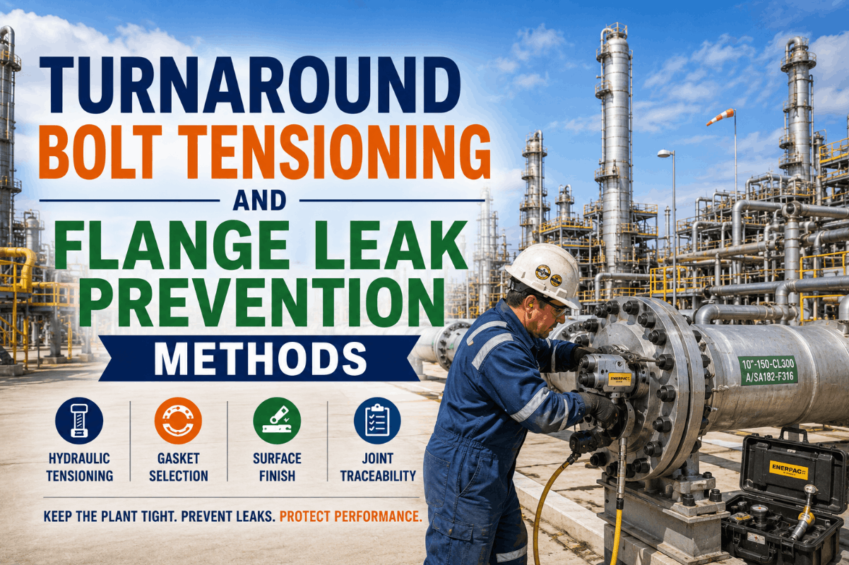
Bolted joints are the most numerous mechanical connections in any oil and gas facility — a typical refinery contains 100,000 or more flanged connections, each one a potential leak path for hazardous process fluids and fugitive emissions. Despite their apparent simplicity, achieving reliable bolted joint performance requires precise control over gasket selection, flange condition, bolt load application, and verification methods that most facilities still manage through manual procedures and paper-based records. The gap between facilities that implement structured joint integrity programs compliant with ASME PCC-1 and those that rely on experienced fitters using hand torque wrenches produces a measurable difference in leak rates, safety incidents, and regulatory compliance costs. To see how iFactory digitizes bolted joint integrity workflows, book a demo with our engineering team.
BOLTED JOINT INTEGRITY · FLANGE MANAGEMENT · OIL AND GAS
Digitize Flange Management and Bolted Joint Integrity Across Your Entire Facility
iFactory's equipment reliability platform manages bolted joint integrity from gasket selection and controlled bolting procedures through torque verification and leak testing with complete traceability for every flanged connection in your plant.
Industry Impact
The Real Cost of Flange Leaks and Fugitive Emissions in Oil and Gas
Flange leaks represent one of the most persistent and costly reliability challenges in oil and gas operations. Unlike equipment failures that produce immediate shutdown events, flange leaks often begin as small, intermittent emissions that escape detection until they escalate into safety incidents, environmental violations, or unplanned outages. The following data quantifies the scale of the bolted joint integrity problem and identifies the specific leverage points where structured joint integrity programs deliver the highest return on investment.
$4.7B
Estimated annual cost of fugitive emissions from flanged connections across US oil and gas operations, including lost product, regulatory fines, and unplanned shutdown remediation expenses
60-80%
Of all flange leaks attributed directly to assembly error — incorrect bolt load, improper sequence, misaligned flanges, or damaged gaskets — not material or design deficiency
90%+
Reduction in flange leak rate achievable when controlled bolting procedures replace manual torque methods, based on comparative data from PCC-1 compliant joint integrity programs
50,000+
Flanged connections requiring quarterly LDAR monitoring at a typical refinery under EPA Subpart VV regulation — each one a recurring inspection cost that structured integrity programs can reduce
Assembly Verification
Flange Joint Assembly Verification — The Inspection Checklist That Prevents Leaks
The majority of flange leaks originate from errors committed before the first bolt is loaded. A structured pre-assembly and assembly verification process, documented in real time, is the most effective intervention available for reducing bolted joint failure rates. The following six verification checkpoints represent the minimum inspection requirements defined by ASME PCC-1 for achieving reliable joint assembly. Each checkpoint must be satisfied and documented before proceeding to the next assembly phase — shortcutting any single step introduces a failure probability that no amount of post-assembly verification can fully recover from.
01
Flange Face Condition Assessment
Inspect both flange faces for radial scratches, gouges, corrugation, weld spatter, and surface damage that could create leak paths across the gasket sealing surface. Verify raised-face finish meets the specified roughness requirement — typically 125 to 250 microinches Ra for most gasket types used in oil and gas service.
125-250 uin Ra
02
Gasket Inspection and Verification
Confirm the gasket type, material, size, and thickness exactly match the flange specification and gasket data sheet. Inspect the gasket for physical damage, stored properly without creasing or compression, and verify it has not exceeded its shelf life or been exposed to conditions that could degrade sealing performance.
Match Spec Exactly
03
Bolt, Nut, and Washer Condition Verification
Inspect all bolts and nuts for thread damage, corrosion, stretching, or deformation that would prevent proper load transfer. Verify bolt grade and material match the specification. Confirm hardened washers are present and in good condition — missing or damaged washers are a frequent contributor to uneven bolt load distribution and subsequent leaks.
Grade Verified
04
Flange Alignment and Gap Verification
Measure flange parallelism using feeler gauges at four or more points around the flange circumference. Maximum allowable gap mismatch is typically 1.5mm for raised-face flanges. Flange misalignment creates uneven gasket compression that produces localized low-stress zones where leaks initiate under process pressure and thermal cycling.
Max 1.5mm Mismatch
05
Bolt Lubricant Application Verification
Confirm the correct lubricant is applied to bolt threads and nut bearing surfaces — not the gasket or flange face. The friction factor of the bolt-nut-washer interface directly determines the relationship between applied torque and resulting bolt tension. Using the wrong lubricant or inconsistent application changes the friction factor and produces unpredictable bolt loads.
Friction Factor Verified
06
Bolt Load Application Sequence Verification
Verify that bolt load is applied in the correct star or cross pattern sequence as specified by ASME PCC-1 for the flange size and bolt count. Confirm the multi-pass sequence is followed — initial snug pass, intermediate pass at a percentage of target load, and final pass to full target load. Sequence deviation is one of the most common assembly errors causing leaks.
Star Pattern Sequence
Bolt Load Parameters
Critical Bolt Load Parameters — What Inspectors Must Measure and Verify
During and after bolt load application, specific parameters must be measured and documented to confirm that the joint has been assembled to the specified bolt load requirements. The relationship between these parameters determines whether the gasket will achieve the required seating stress to maintain a seal under operating conditions. The following five parameters represent the most critical measurements in a bolted joint integrity verification program, each with distinct measurement methods and acceptance criteria that must be understood by every joint integrity inspector.
Bolt Torque
Acceptable Range: Per PCC-1 calculation for specified bolt stress and friction factor
Method: Calibrated torque wrench or hydraulic torque tool with certificate
Critical: Torque alone is indirect — actual bolt tension varies with friction factor
Bolt Tension (Hydraulic)
Acceptable Range: Target bolt stress per PCC-1 Appendix J for flange class and gasket type
Method: Hydraulic bolt tensioner with calibrated pressure gauge and load cell
Critical: Direct measurement — preferred method for critical and high-pressure flanges
Bolt Elongation (Stretch)
Acceptable Range: Calculated from target bolt stress, bolt length, and elastic modulus
Method: Ultrasonic bolt measurement or mechanical dial indicator per PCC-1
Critical: Most accurate direct measurement — verifies actual bolt stress independent of friction
Gasket Seating Stress
Acceptable Range: Between gasket minimum seating stress and maximum allowable stress
Method: Calculated from total bolt load minus flange reaction, divided by gasket area
Critical: Below minimum = leak risk; above maximum = gasket crush and extrusion damage
Flange Rotation and Gap
Acceptable Range: Uniform gap at all points, within flange tolerance for gasket type
Method: Feeler gauge measurements at minimum four points around flange circumference
Critical: Non-uniform gap indicates flange misalignment or uneven bolt load distribution
Service Classification
High-Risk vs Standard Flange Service — How Joint Integrity Requirements Differ
Not all flanged connections in an oil and gas facility require the same level of joint integrity controls. Applying high-specification controlled bolting procedures to every low-pressure utility flange wastes resources, while applying standard procedures to high-pressure hydrogen service flanges creates unacceptable safety and environmental risk. The following comparison defines the practical differences in joint integrity requirements between high-risk and standard service classifications, enabling operators to allocate inspection and assembly resources proportionally to the actual consequence of failure at each connection point.
High-Risk vs Standard Flange Joint Integrity Requirements
Failure Analysis
Bolted Joint Failure Mode Identification — Symptom, Root Cause, and Corrective Action
When flanged connections leak, accurate failure mode identification determines whether the corrective action addresses the actual root cause or merely provides a temporary repair that will fail again under the same operating conditions. The following five failure modes represent the most frequently encountered bolted joint degradation types in oil and gas service. Each has distinct observable symptoms at the connection point, identifiable root causes that joint integrity inspection should have prevented, and specific corrective actions that address the underlying mechanism rather than simply replacing the gasket and re-torquing.
Gasket Blowout
Visual Symptom
Sudden, often violent escape of process fluid through the flange gap. Gasket material may be visibly extruded from the flange interface or completely ejected. Typically occurs during initial pressurization or pressure surge events.
Root Cause
Insufficient bolt load to seat the gasket before pressurization, incorrect gasket selection for the pressure class, excessive flange gap from misalignment, or gasket damage during installation that created a weak point in the seal.
Corrective Action
Verify gasket selection matches pressure and temperature class, correct flange alignment before re-assembly, apply bolt load using controlled bolting procedure with verified target stress, and confirm gasket seating stress meets minimum requirements before pressurization.
Fugitive Emission Weep
Visual Symptom
Small, continuous or intermittent leak detected by LDAR monitoring — often not visible to the naked eye. Detected as concentration readings above regulatory thresholds using portable analyzers or fixed monitoring systems during quarterly surveys.
Root Cause
Bolt load relaxation from thermal cycling, gasket creep under sustained compression, uneven bolt load distribution from incorrect assembly sequence, or flange rotation from piping loads that exceeded allowable values.
Corrective Action
Measure current bolt load using ultrasonic methods to identify relaxed bolts, verify piping loads are within allowable flange limits, re-tension using correct sequence, and implement scheduled re-torque checks after thermal cycles for similar service flanges.
Gasket Extrusion
Visual Symptom
Gasket material visibly protruding from the inner or outer diameter of the flange interface. The extruded portion may appear compressed, shredded, or torn. Often accompanied by progressive leak development as the gasket sealing area reduces.
Root Cause
Bolt load exceeded maximum gasket stress causing material flow into the flange gap, incorrect gasket thickness for the flange clearance, excessive internal pressure pushing gasket into the bore, or gasket material with insufficient creep resistance for the service conditions.
Corrective Action
Verify bolt load does not exceed gasket manufacturer maximum stress rating, confirm gasket thickness and inner diameter are correct for the flange size and class, and select gasket material with appropriate creep resistance if service temperature and pressure conditions warrant.
Bolt Stress Corrosion Cracking
Visual Symptom
Bolts may appear intact externally but have developed internal or surface-initiated cracks that reduce their load-carrying capacity. Often discovered during re-torque attempts when bolts fail at loads well below their rated capacity. May be accompanied by discoloration or corrosion product on bolt surfaces.
Root Cause
Bolt material susceptible to stress corrosion cracking in the service environment — common with high-strength bolting in H2S-containing service, or when bolts are tensioned above their stress corrosion cracking threshold in the presence of corrosive species.
Corrective Action
Replace bolts with material rated for the sour service environment per NACE MR0175, verify bolt stress is maintained below the SCC threshold for the material and environment, and implement periodic bolt material verification in susceptible service locations.
Flange Face Damage
Visual Symptom
Visible scoring, gouging, warping, or corrosion pitting on the flange sealing surface. Leaks may occur at specific locations corresponding to damage points on the flange face. Repeated gasket replacement at the same flange without resolution of the leak is a strong indicator.
Root Cause
Gasket material welding or bonding to the flange face during previous service, mechanical damage from improper gasket removal using chisels or grinders, corrosion from process chemical exposure during previous leak events, or thermal warping from uneven heating or fire exposure.
Corrective Action
Inspect flange face with straightedge and surface finish comparator, re-machine or re-surface if damage is within allowable tolerance, replace flange if damage exceeds repair limits, and implement proper gasket removal procedures to prevent face damage during future maintenance.
Verification Methods
Joint Integrity Verification Methods — When to Apply Each Technique
Bolted joint integrity verification requires selecting the correct measurement method for each stage of the joint lifecycle. Applying a verification method at the wrong stage produces unreliable data, while omitting a required method at a critical stage creates an undocumented quality gap. The following matrix maps each primary verification method to the lifecycle stages where it delivers essential quality assurance value for bolted joint integrity programs in oil and gas service. For a guided walkthrough of how iFactory structures these verifications digitally, book a demo with our engineering team.
Verification Method
Pre-Assembly
Assembly
Post-Assembly
In-Service
Ultrasonic Bolt Measurement
Gasket Stress Calculation
Primary Application
Secondary Application
Not Typically Applied
Standards Reference
Governing Standards for Bolted Joint Integrity in Oil and Gas
Bolted joint integrity programs in oil and gas are governed by a framework of standards from ASME, API, ASTM, and EN that define everything from bolt load calculation procedures to gasket selection criteria and assembly documentation requirements. Inspectors and engineers must be proficient in the specific standards referenced in each flange specification, as the acceptance criteria and calculation methods vary significantly between standards. The following reference cards summarize the primary standards most frequently encountered in bolted joint integrity programs for offshore and onshore oil and gas facilities.
ASME PCC-1
Guidelines for Pressure Boundary Bolted Flange Joint Assembly
The primary standard governing bolted joint assembly procedures including bolt load calculation, tightening sequences, tool selection, gasket selection guidance, and documentation requirements. PCC-1 is the foundational reference for all joint integrity programs in pressure equipment service.
ASME B16.5 / B16.47
Pipe Flanges and Flanged Fittings
Defines flange dimensions, pressure-temperature ratings, facing types, and bolting requirements for steel pipe flanges. B16.5 covers NPS 1/2 through 24 and B16.47 covers NPS 26 through 60. These standards establish the physical parameters that bolt load calculations are based on.
ASME PCC-3
Inspection Planning Using Risk-Based Methods for Pressure Boundary Bolted Flange Joints
Provides a risk-based framework for prioritizing flange inspection and integrity verification activities based on consequence of failure and likelihood of leak. Enables operators to allocate joint integrity resources proportionally to risk rather than applying uniform inspection intensity to all connections.
EN 1591-1
Flanges and Their Joints — Design Rules for Gasketed Circular Flange Connections
The European standard for detailed flange joint design and analysis that accounts for flange flexibility, gasket behavior, and bolt load interaction more rigorously than ASME methods. Required for non-standard flange designs and increasingly referenced for critical service joint analysis.
API 6A / API 17D
Wellhead and Christmas Tree Equipment / Subsea Wellhead and Tree Equipment
Define bolting and flange requirements for upstream wellhead and subsea equipment where bolted joint integrity is critical for well control safety. These specifications include mandatory bolt load verification and leak testing requirements that exceed standard process piping requirements.
ASTM F2378
Test Method for Measuring Bolt Tension Using Ultrasonic Measurement
Specifies the procedure for using ultrasonic pulse-echo technology to measure bolt elongation and calculate bolt stress. This is the reference method for ultrasonic bolt load verification, which provides the most accurate direct measurement of bolt stress available in field conditions.
Frequently Asked Questions
Bolted Joint Integrity and Flange Management — Frequently Asked Questions
What is the difference between torque-controlled and tension-controlled bolting for flange assembly?
Torque-controlled bolting applies a rotational force to the nut and relies on the relationship between torque, friction factor, and bolt tension to achieve the target bolt stress — but because friction factor varies with lubricant condition, surface finish, and temperature, the actual bolt tension can vary by plus or minus 25 to 30 percent from the calculated value. Tension-controlled bolting uses hydraulic tensioners that apply a direct axial stretch to the bolt, producing bolt load accuracy within plus or minus 5 percent regardless of friction variation. For high-risk flange service where precise bolt load is critical, tension-controlled methods are the preferred approach. To see how iFactory manages both methods within a single digital workflow,
book a demo with our engineering team.
How does ASME PCC-1 define the bolt load calculation procedure for flanged joints?
ASME PCC-1 provides a systematic procedure in Appendix J that calculates the required bolt load based on four design conditions: minimum seating load to compress the gasket, hydrostatic end force from design pressure, gasket margin to maintain seal under operating conditions, and flange limit checks to ensure the bolt load does not exceed the flange's structural capacity. The target bolt load is the highest value from these four checks, and the procedure then converts this load into either a torque value for torque-controlled assembly or a hydraulic pressure for tension-controlled assembly. The calculation must account for the specific gasket type, flange class, bolting material, and operating temperature. For support implementing PCC-1 calculations in a digital environment,
contact support.
Why do flanges that were assembled correctly initially develop leaks after thermal cycling?
Thermal cycling causes differential expansion between the bolts, flanges, and gasket that changes the bolt load distribution over time. As the flange heats up, the bolts typically elongate more than the flange compresses, reducing the gasket stress below the minimum required to maintain the seal. When the flange cools, the bolt load may not fully recover due to gasket creep — a permanent deformation of the gasket material under sustained compression at elevated temperature. After multiple thermal cycles, the cumulative bolt load relaxation can drop below the minimum gasket seating stress, and the joint begins to leak. This is why PCC-1 recommends post-thermal-cycle bolt load verification for critical service flanges. To explore how iFactory tracks bolt load changes across thermal cycles,
book a demo.
What role does bolt lubrication play in flange joint integrity and why is it so critical?
Bolt lubrication applied to the threads and nut bearing surfaces determines the friction factor in the torque-to-tension relationship — a variation of plus or minus 0.05 in friction factor can change the resulting bolt tension by 15 to 25 percent at the same applied torque. Using the wrong lubricant, applying it inconsistently across bolts, or omitting lubrication entirely means that the torque values specified by the PCC-1 calculation will produce unpredictable and uneven bolt loads across the flange. This uneven loading is a primary cause of gasket stress concentration that leads to localized sealing failure and fugitive emissions. The lubricant must match the specification used in the bolt load calculation, and its application must be verified by the inspector before assembly begins. For support implementing lubrication verification procedures,
contact support.
How should a facility prioritize which flanged connections receive the highest level of joint integrity controls?
ASME PCC-3 provides a risk-based framework that classifies flanged connections by consequence of failure and likelihood of leak, producing a risk ranking that determines the appropriate level of assembly controls, inspection frequency, and documentation requirements for each connection. High-risk classifications typically include flanges in toxic or highly flammable service, connections above certain pressure and temperature thresholds, flanges with a history of repeated leaks, and connections where failure would result in fire, explosion, or environmental release. The risk-based approach ensures that controlled bolting, hydraulic tensioning, and post-assembly verification resources are concentrated on the connections where they provide the greatest safety and compliance value rather than applied uniformly across all flanges regardless of consequence. To see how iFactory implements PCC-3 risk-based flange prioritization,
book a demo.
BOLTED JOINT INTEGRITY · FLANGE MANAGEMENT · OIL AND GAS
Build a Digital Flange Management Program That Eliminates Unplanned Joint Leaks
iFactory's platform digitizes every stage of bolted joint integrity — from gasket selection and PCC-1 bolt load calculations through controlled bolting execution, ultrasonic verification, and LDAR tracking with complete audit traceability for every flanged connection.