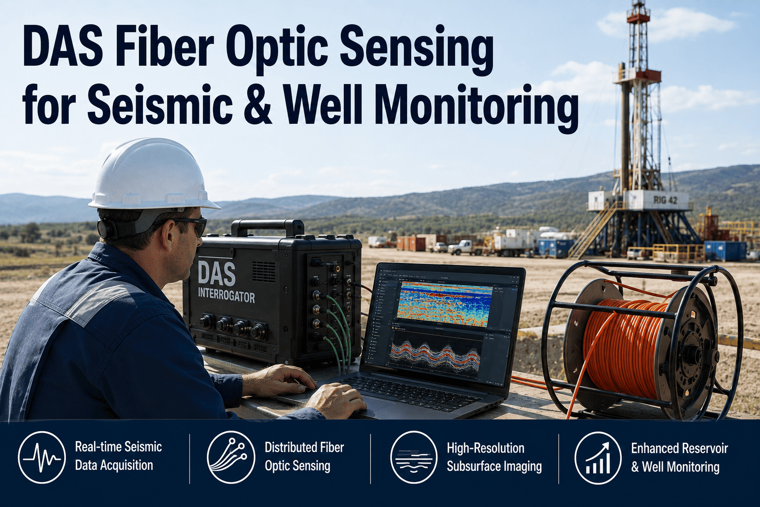
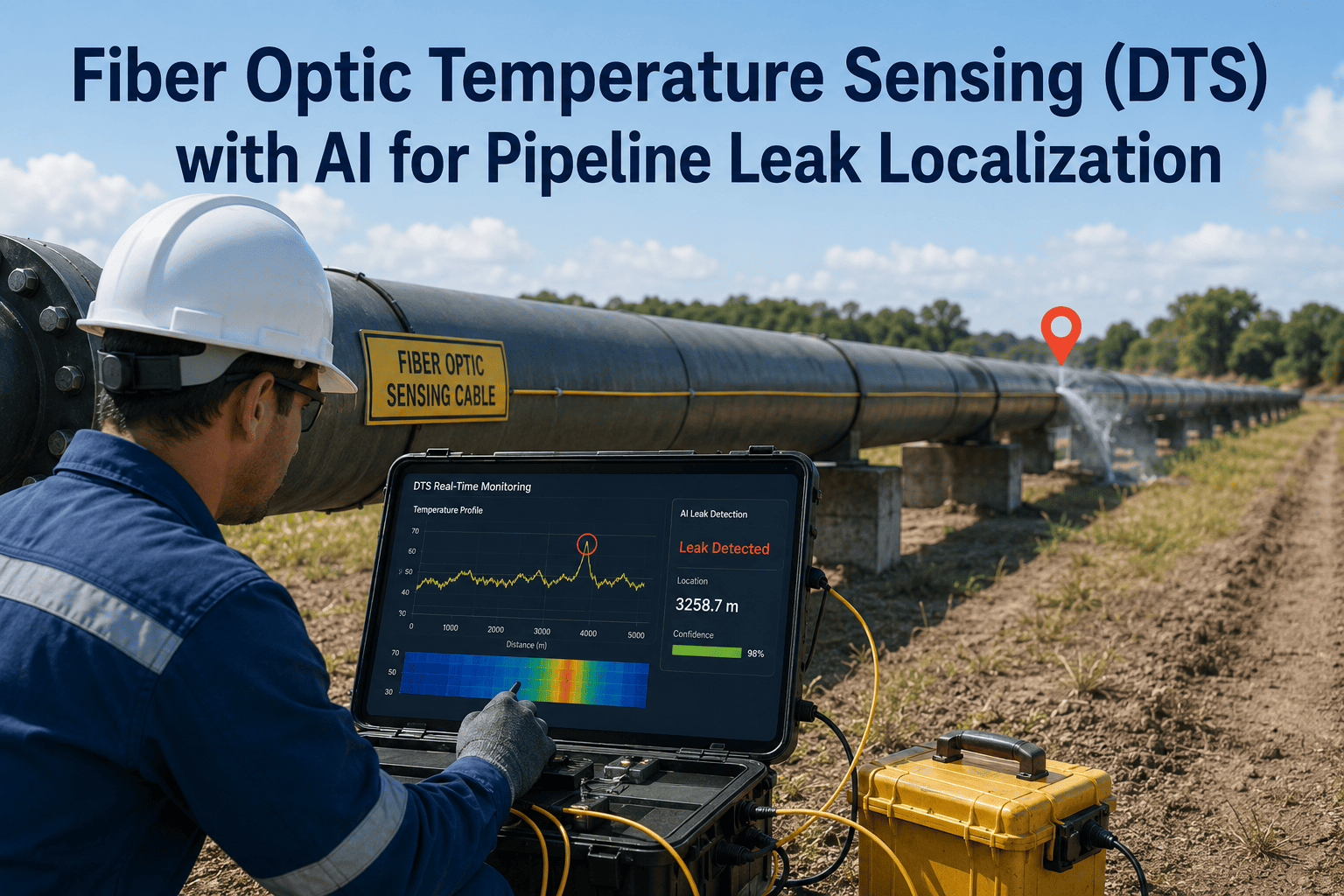
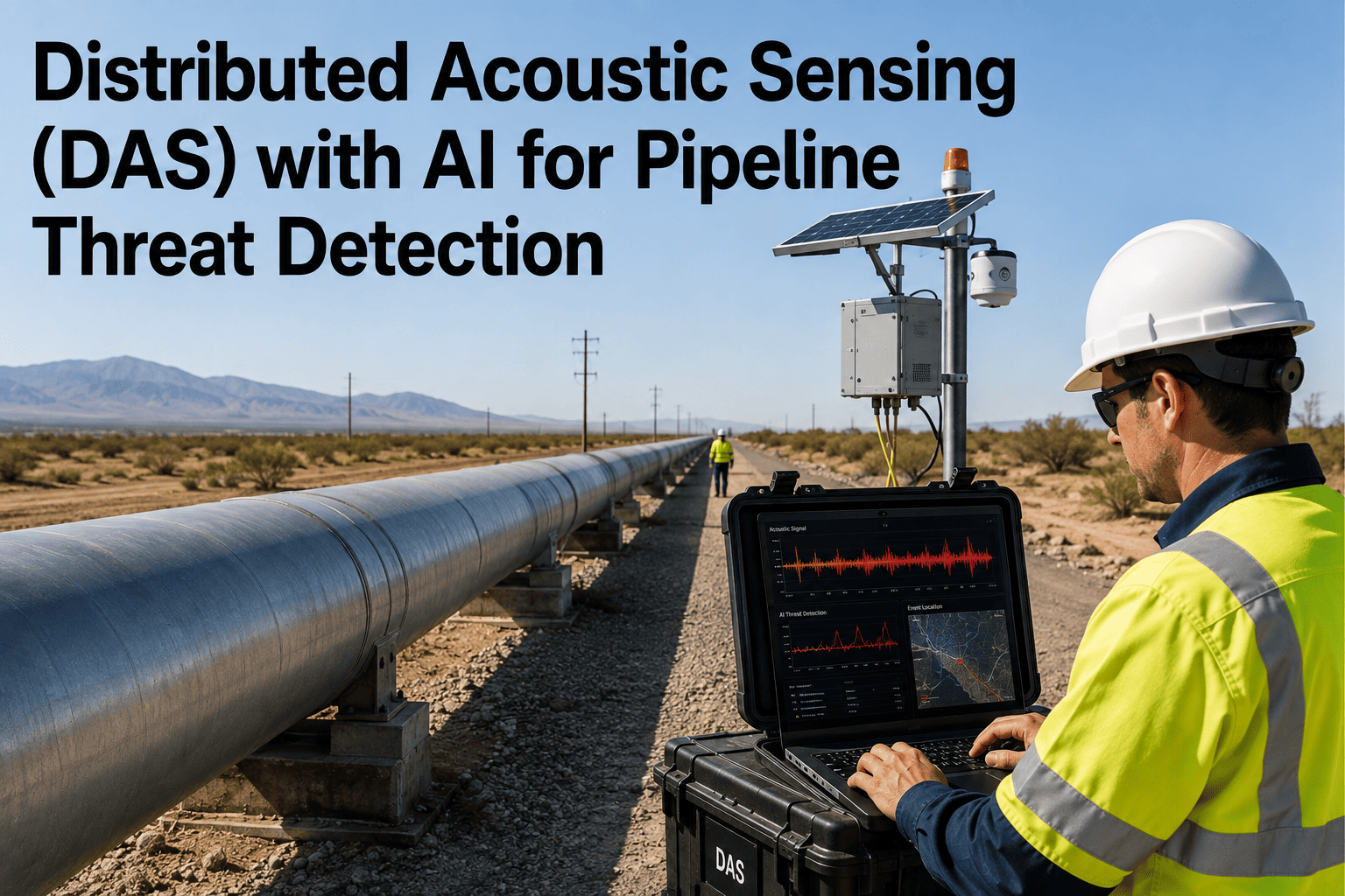
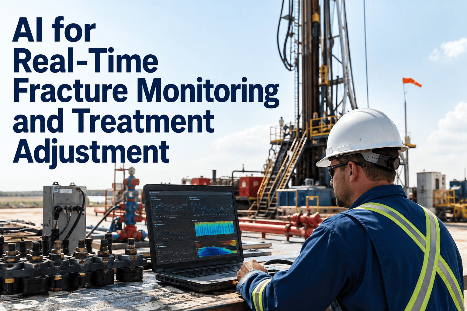
Distributed acoustic sensing transforms a standard fiber optic cable into a continuous array of thousands of acoustic sensors by analyzing the backscattered light patterns that shift when acoustic energy disturbs the glass fiber along the wellbore. Unlike conventional downhole sensors that require individual electronic components, housing, and cable connections at each measurement point, DAS uses the fiber itself as the sensing medium, which means a single cable installed behind casing provides measurement density that would cost millions to achieve with conventional geophones. The technology enables vertical seismic profiling with meter-scale spatial sampling, continuous production flow profiling along the entire completed interval, and real-time monitoring of hydraulic fracture growth during stimulation treatments. The primary challenge has never been the sensing capability of the fiber but rather the massive data volume that thousands of channels generate and the specialized processing required to convert raw strain-rate measurements into interpretable signals. You can book a demo to see how iFactory processes DAS data into actionable well and reservoir intelligence.
OIL AND GAS · SEISMIC DATA ANALYTICS · FIBER OPTIC SENSING
DAS Fiber Optic Sensing: Turn Every Meter of Fiber Into a Seismic and Flow Sensor
Convert existing or newly installed fiber optic cables into thousands of virtual sensors for VSP, production monitoring, fracture diagnostics, and well integrity evaluation without any downhole electronics.
HOW DAS WORKS
A Single Fiber Optic Cable Becomes Thousands of Virtual Sensors Along the Full Wellbore
The DAS interrogator unit at surface sends laser pulses down the fiber and analyzes the backscattered light returning from every gauge length along the cable. When acoustic energy from a seismic source, fluid flow, or mechanical vibration reaches the fiber, it creates a tiny strain that shifts the backscatter pattern. The interrogator measures this shift at each gauge length independently, producing a continuous acoustic profile from surface to total depth. The visualization below shows the four depth zones where DAS provides distinct monitoring value along a typical wellbore.
Surface Facilities and Ground Movement
Cement Bond and Casing Condition
Inflow Profiling and Water Cut Detection
Fracture Growth and VSP Reflections
0 - 500 m
500 - 1,500 m
1,500 - 3,000 m
3,000 - 4,500 m
Surface Zone: Equipment vibration, leak detection, surface seismic
Intermediate Zone: Cement evaluation, casing inspection, near-surface gas
Production Zone: Flow profiling, water entry points, artificial lift monitoring
Reservoir Zone: Hydraulic fracture monitoring, VSP imaging, cross-well sensing
MONITORING APPLICATIONS
Four Critical Applications Enabled by Distributed Acoustic Sensing in a Single Installation
Conventional monitoring requires separate sensor deployments for each application: geophones for VSP, spinners for flow profiling, and tiltmeters for fracture monitoring. DAS provides all four monitoring capabilities from the same fiber installation simultaneously, switching between applications in the data processing stage rather than the hardware deployment stage.
Fiber Optic VSP
Full Wellbore Coverage
DAS replaces downhole geophone arrays for vertical seismic profiling by recording the full seismic wavefield at meter-scale sampling. The dense spatial sampling resolves thin beds and velocity variations that conventional 50-meter spaced geophones alias, producing higher-resolution seismic images near the wellbore for tieing surface seismic to well log data.
Production Flow Profiling
Producing Interval
Acoustic energy from fluid flow through perforations creates characteristic strain signatures on the fiber that DAS detects and quantifies. The continuous profile shows which perforation clusters are contributing, where water or gas is entering, and how flow distribution changes over time without running any tools into the well.
Hydraulic Fracture Diagnostics
Reservoir Section
During stimulation treatments, DAS detects the acoustic emissions from rock failure at the fracture face and measures the strain caused by fracture opening along the wellbore. The real-time strain profile shows which perforation clusters are taking fluid, whether fractures are growing symmetrically, and when fracture height is extending beyond the target zone.
Well Integrity Monitoring
Full Wellbore Coverage
DAS detects acoustic anomalies associated with casing leaks, cement channeling, sustained casing pressure sources, and fluid movement behind casing. Permanent fiber installation enables continuous integrity monitoring without periodic intervention runs, detecting issues weeks or months earlier than conventional surveillance methods.
Your Fiber Optic Cable Is Already Recording Data That Conventional Sensors Cannot Match
iFactory's DAS analytics platform processes the massive strain-rate data streams from your fiber into VSP images, flow profiles, fracture maps, and integrity alerts from a single installation. Book a demo to see DAS data processed into actionable results.
SENSING DENSITY
Channel Spacing That Conventional Downhole Sensor Arrays Cannot Physically Achieve
The fundamental advantage of DAS over conventional sensors is spatial sampling density. A conventional VSP array deploys 40 to 80 geophones spaced 15 to 50 meters apart. DAS provides a sensor at every gauge length along the fiber, typically 1 to 2 meters, producing hundreds to thousands of measurement points from the same wellbore. The ruler comparison below visualizes this density difference at the same physical scale.
Approximately 4,500 channels over 4,500m wellbore
Approximately 90 sensors over 4,500m wellbore
50x
More Measurement Points
Zero
Downhole Electronics Required
Permanent
Installation Capability
DATA PROCESSING
From Raw Strain-Rate Signals to Interpretable Seismic and Flow Data in Six Processing Stages
Raw DAS data requires specialized processing that differs significantly from conventional seismic data processing because the measurements are strain rate rather than particle velocity, the spatial sampling is extremely dense but non-uniform, and the signal-to-noise characteristics vary along the fiber depending on coupling quality and cable installation conditions. The pipeline below shows the six stages that iFactory's platform applies to convert raw DAS recordings into interpretation-ready data products.
01
Raw DAS Acquisition
Strain-rate time series recorded at each gauge length by the surface interrogator unit, including all ambient noise, signal, and coupling variations along the fiber path.
02
Data Conditioning and Calibration
Gain normalization to correct for fiber attenuation, spatial resampling to uniform gauge length, removal of instrumental noise and temperature drift, and quality flagging of poorly coupled sections.
03
Seismic Wavefield Extraction
Source waveform correlation for VSP applications, moveout correction to flatten upgoing and downgoing wavefields, and separation of P-waves and S-waves using the dense spatial sampling that only DAS provides.
04
Flow Signal Extraction
Low-frequency strain analysis to identify flow-induced acoustic energy, acoustic intensity computation along the wellbore, and classification of flow signatures by type including single-phase, multiphase, and gas-liquid patterns.
05
Interpretation Integration
VSP image migration and tie to surface seismic, flow profile computation with rate allocation per perforation cluster, fracture geometry estimation from strain patterns, and integrity anomaly classification.
06
Decision Support Output
Actionable reports for well intervention planning, completion design optimization, production allocation updates, and integrity risk assessment delivered through the analytics dashboard with historical trend tracking.
HEAD TO HEAD
Distributed Acoustic Sensing vs Conventional Downhole Sensor Arrays
The table below compares DAS fiber optic sensing against conventional downhole geophones and production logging tools across the operational dimensions that determine which monitoring approach is appropriate for each wellbore monitoring objective.
DEPLOYMENT RESULTS
Measured Outcomes From DAS Monitoring Programs Across Multiple Basin Types
These figures reflect measured outcomes from operators who deployed permanent DAS fiber installations for combined VSP, production monitoring, and integrity surveillance, with each result tracked over a minimum twelve-month production period after fiber installation.
4,800
Virtual Channels
Measurement Points Per Well vs 60 Conventional Sensors
A single fiber installation replaced the equivalent of 80 separate sensor deployment runs, providing continuous data from 4,800 channels that would require 4,800 individual geophone installations to match at conventional spacing.
91%
Accuracy
Flow Profile Match to Conventional PLT Reference Measurements
DAS-derived flow profiles matched conventional production logging tool measurements within 9 percent across 12 comparison runs, validating DAS as a permanent flow surveillance alternative to periodic PLT campaigns.
$890K
Annual Savings
Per Well From Eliminated Intervention Runs and Optimized Interventions
Combined savings from eliminated wireline logging runs, reduced well intervention frequency through continuous monitoring, and optimized workover targeting based on DAS flow profile changes over time.
14 Weeks
Earlier Detection
Of Casing Integrity Issues Compared to Conventional Surveillance Schedules
Continuous DAS integrity monitoring detected casing leaks and sustained casing pressure sources an average of 14 weeks earlier than they would have been identified through conventional periodic monitoring programs.
Thousands of Channels Are Recording Right Now on Your Fiber — The Data Just Needs Processing
iFactory's DAS analytics platform transforms raw strain-rate data from your fiber optic installation into VSP images, flow profiles, fracture diagnostics, and integrity reports through an automated processing pipeline. Book a demo to see your DAS data converted into well intelligence.
FREQUENTLY ASKED QUESTIONS
Questions From Reservoir and Production Engineers About DAS Fiber Optic Monitoring
Can DAS replace conventional geophones for VSP applications, or is the signal quality still insufficient?
DAS VSP signal quality has improved dramatically over the past five years through advances in interrogator design, fiber cable construction, and AI-based noise reduction processing. For walkaway VSP and zero-offset VSP applications, DAS now produces seismic images that are comparable to conventional geophone VSP for structural interpretation and surface seismic tie purposes, though the per-channel signal-to-noise ratio remains lower than high-performance geophones in quiet wellbore conditions. The advantage of DAS is that the dense spatial sampling compensates for lower per-channel SNR through spatial stacking, and DAS provides data from the entire wellbore including intervals where geophones cannot be positioned due to wellbore geometry or obstruction.
Book a demo to compare DAS and geophone VSP quality on your well data.
What fiber optic cable type is required for DAS, and can existing telecommunications fiber be used?
DAS works with standard single-mode fiber, but the cable construction and installation method significantly affect the acoustic coupling and therefore the data quality. Purpose-built DAS cables with tight-buffer coatings, stainless steel or carbon fiber reinforcement, and optimized outer jackets provide the best acoustic coupling to the wellbore environment. Standard telecommunications fiber can detect strong acoustic events but typically produces lower signal quality for weak seismic reflections due to the loose tube construction that decouples the fiber from acoustic energy. For new installations, iFactory recommends specifying DAS-optimized cable based on the wellbore conditions and primary monitoring objectives. For existing fiber, a pilot recording can determine whether the installed cable provides adequate quality for the intended applications.
Contact our support team to discuss fiber cable selection for your well conditions.
How does DAS flow profiling compare to conventional production logging tools for rate allocation?
DAS flow profiling provides relative flow contribution along the wellbore by measuring the acoustic energy generated by fluid flow through perforations, which correlates with flow rate but does not directly measure absolute flow volume like a spinner flowmeter. For rate allocation between perforation clusters, DAS provides reliable relative contributions that show which clusters are producing and how the distribution changes over time, which is sufficient for many production optimization decisions. When absolute rate measurement is required, DAS flow profiles can be calibrated using a single conventional PLT run to establish the relationship between acoustic intensity and flow rate, after which DAS provides continuous calibrated profiles without additional PLT interventions.
Book a demo to see DAS flow profiling calibrated to your well conditions.
What data volume does DAS generate, and how is it managed for continuous monitoring applications?
A typical DAS deployment with 4,000 channels recorded at 1 millisecond sample rate generates approximately 32 gigabits per second of raw data, which translates to roughly 3.5 terabytes per hour or 84 terabytes per day of continuous recording. This data volume makes continuous raw data storage impractical for long-term monitoring, so iFactory's platform applies real-time edge processing that extracts only the relevant data products such as seismic gathers, flow profile summaries, and integrity alerts while discarding the raw strain-rate data after processing. The platform reduces the long-term storage requirement by over 99 percent while preserving all interpretable information, making permanent DAS monitoring operationally feasible without building dedicated high-capacity data infrastructure.
Contact our support team to discuss data management architecture for your DAS deployment.
Can DAS monitor multiple wells from a single fiber installation using surface or cross-well configurations?
DAS can monitor multiple wells from a single fiber when the fiber is deployed in a surface configuration above the wellheads or in a horizontal well that passes near multiple vertical wellbores for cross-well monitoring. Surface DAS above wellheads detects acoustic energy from production and injection operations at each well but with significantly reduced signal quality compared to downhole deployment because the acoustic energy must travel through the overburden and near-surface materials that attenuate high frequencies. Cross-well DAS where a horizontal fiber in one well monitors acoustic energy from adjacent vertical wells provides better coupling than surface deployment but requires the wells to be within a few hundred meters for reliable signal detection. For multi-well pads, the most effective approach is installing dedicated fiber in each wellbore and connecting them to a shared interrogator unit at surface.
Book a demo to evaluate multi-well DAS configurations for your pad layout.
The Fiber Is in the Ground — Every Day Without Processing Is a Day of Wasted Monitoring Data
iFactory's platform processes your DAS strain-rate recordings into VSP images, flow profiles, fracture maps, and integrity alerts through an automated pipeline that handles the massive data volume without manual intervention. Book a demo to start extracting value from your fiber optic investment.