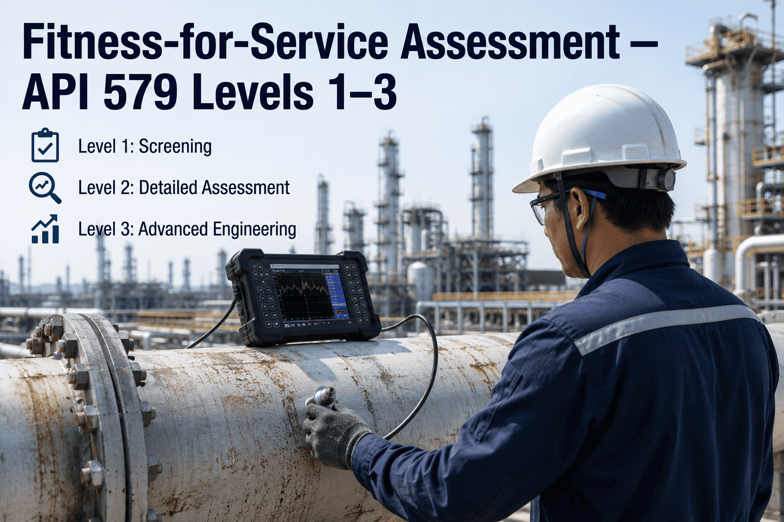
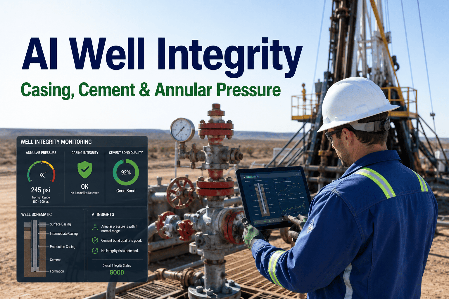
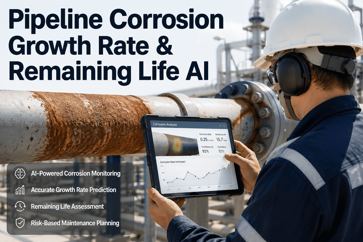
Pressure equipment in oil and gas facilities operates under extreme conditions that inevitably introduce damage over time — corrosion, cracking, denting, and creep gradually degrade structural integrity long before visible failure occurs. Fitness-for-Service (FFS) assessment, standardized through API 579/ASME FFS-1, provides a rigorous engineering methodology to evaluate whether damaged equipment can safely continue operating at its original design conditions. Rather than automatically replacing components that show damage indications, FFS applies proven analytical techniques across three progressive assessment levels to quantify actual remaining strength and make evidence-based run-repair-replace decisions. For oil and gas operators managing aging infrastructure, this approach has become the most cost-effective pathway to maintaining operational continuity and regulatory compliance. To explore how FFS workflows integrate with digital equipment reliability systems, book a demo with our engineering team.
API 579 FFS · OIL AND GAS · EQUIPMENT RELIABILITY
Evaluate Damaged Equipment with Confidence Using API 579 Fitness-for-Service
iFactory's equipment reliability platform streamlines FFS assessment workflows from damage detection and data collection through Level 1, 2, and 3 analysis to documented run-repair-replace decisions with full audit traceability.
Fundamentals
What Is Fitness-for-Service Assessment and Why It Matters for Oil and Gas Equipment
Fitness-for-Service is a structured engineering evaluation that determines whether pressure equipment containing flaws, damage, or deterioration can continue to operate safely at specified conditions for a defined period. Unlike simple thickness-based replacement criteria that often lead to unnecessary capital expenditure, FFS uses the actual remaining strength of the damaged component as the basis for operational decisions. The methodology is codified in API 579/ASME FFS-1, which is the internationally recognized standard for performing these assessments across the oil and gas, petrochemical, and power generation industries.
The core value proposition of FFS is the run-repair-replace decision framework. When inspection reveals damage that exceeds original design allowances, FFS provides the engineering basis to determine whether the component can continue operating (run), requires remediation to restore integrity (repair), or must be removed from service (replace). This decision is supported by quantitative analysis rather than conservative default assumptions, and the result is typically a significant reduction in unnecessary equipment replacement while maintaining or improving safety margins.
01
Engineering Evaluation
Quantitative analysis of damaged pressure equipment using established mathematical models and material science principles to determine actual remaining structural capacity
02
API 579/ASME FFS-1 Standard
The internationally accepted code that defines assessment procedures, acceptance criteria, and documentation requirements for evaluating damaged pressure-containing equipment
03
Run-Repair-Replace Decision
Structured decision outcome that determines whether damaged equipment can continue operating, requires restoration intervention, or must be removed from service entirely
04
Replacement Cost Avoidance
Primary financial driver — industry data shows 60 to 75 percent of equipment flagged for replacement by simple criteria passes Level 2 FFS assessment and can safely continue operation
Assessment Levels
API 579 Assessment Levels 1, 2, and 3 — A Progressive Analytical Framework
API 579 organizes FFS assessment into three progressively complex levels. Each level uses more sophisticated analytical techniques and produces less conservative but more accurate results. The standard is designed so that assessments begin at Level 1 and only progress to higher levels when the component does not satisfy the screening criteria at the current level. This progressive approach ensures that simple cases are resolved quickly with minimal engineering effort while complex cases receive the detailed analysis they require. Understanding the capabilities and limitations of each level is essential for planning assessment scope, timeline, and resource allocation.
L1
Screening Assessment
Level 1 — Point-by-Point Screening
Applies conservative screening criteria using simplified formulas, look-up tables, and thickness measurements at the location of maximum damage. The assessment evaluates the remaining strength factor (RSF) against a minimum acceptable value of 0.9 for most damage types. Level 1 is intentionally conservative — a component that fails Level 1 may still pass at a higher level.
L2
Analytical Assessment
Level 2 — Detailed Analytical Evaluation
Applies more sophisticated analytical techniques that account for the actual stress distribution in the component, interaction between damage and structural geometry, and material properties at operating conditions. Level 2 uses closed-form solutions and stress analysis to calculate a more accurate remaining strength factor. This level typically produces 15 to 30 percent less conservative results than Level 1, which frequently changes the run-repair-replace decision outcome.
L3
Advanced Assessment
Level 3 — Numerical Analysis and FEA
Employs advanced numerical methods including finite element analysis (FEA) to model the exact geometry, loading, damage configuration, and material behavior of the component. Level 3 provides the most accurate assessment results and is required when Level 2 methods cannot adequately represent the structural behavior — common in complex geometries, interacting damage mechanisms, and high-consequence applications where maximum accuracy is needed.
Damage Mechanisms
Damage Types Evaluated Under API 579/ASME FFS-1
API 579 addresses a comprehensive range of damage mechanisms commonly encountered in oil and gas pressure equipment. Each damage type has a dedicated assessment part within the standard, with specific procedures, acceptance criteria, and analytical methods tailored to the physics of that damage mechanism. The following six damage categories represent the most frequently assessed types in upstream, midstream, and downstream oil and gas operations. Selecting the correct assessment part is the critical first step in any FFS evaluation — applying the wrong damage model produces unreliable results regardless of the assessment level used.
Part 4
General Metal Loss
Uniform or near-uniform wall thinning across a significant portion of the component surface caused by corrosion or erosion processes operating over extended service periods
Corrosion / Erosion
Part 5
Local Metal Loss
Localized thinning concentrated in a defined area, such as under insulation corrosion, localized erosion at pipe bends, or corrosion beneath damaged coatings and linings
Localized Thinning
Part 6
Pitting Corrosion
Discrete pits of varying depth and density on the internal or external surface, commonly caused by microbiologically influenced corrosion, acidic environments, or chloride attack
Pitting / MIC
Part 7
Blistering and Hydrogen Damage
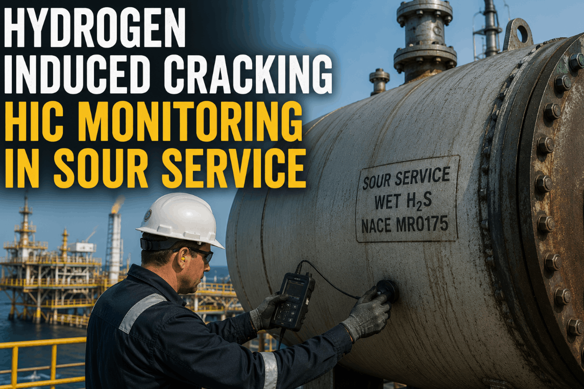
Hydrogen-induced damage mechanisms including hydrogen blistering, hydrogen-induced cracking, stress-oriented hydrogen-induced cracking, and stepwise cracking in wet H2S environments
HIC / SOHIC / Blisters
Part 8
Weld Misalignment and Distortion
Out-of-roundness, angular misalignment, and shell distortions at weld joints that create local stress concentrations exceeding the levels assumed in original design calculations
Fabrication / Weld
Part 9
Crack-Like Flaws
Planar defects including surface cracks, embedded cracks, and through-wall cracks detected by NDT methods, assessed using fracture mechanics principles including stress intensity factor and J-integral approaches
Fatigue / Cracking
Level Comparison
Level 1 vs Level 2 vs Level 3 — Comprehensive Assessment Comparison
The following comparison table provides a detailed side-by-side evaluation of all three API 579 assessment levels across the parameters most relevant to oil and gas operators planning an FFS program. Understanding these differences enables accurate scope definition, resource planning, and timeline estimation before assessment work begins. Selecting the appropriate starting level and anticipating potential escalation to higher levels is a critical planning activity that directly affects project cost and schedule outcomes.
API 579 Assessment Level Comparison for Oil and Gas Equipment
Decision Framework
The Run-Repair-Replace Decision Framework Powered by FFS Analysis
The entire purpose of a Fitness-for-Service assessment is to arrive at a defensible, code-compliant run-repair-replace decision for damaged equipment. This decision framework is not a subjective engineering judgment — it is a structured process where the calculated remaining strength factor, flaw size relative to critical flaw dimensions, and predicted remaining life are compared against explicit acceptance criteria defined in API 579. The following three-stage framework represents how leading oil and gas operators structure this decision process to ensure consistency, defensibility, and regulatory compliance across their entire equipment fleet.
1
Detect and Quantify Damage
Execute targeted inspection using appropriate NDT methods to identify, locate, and measure all damage indications. Compile thickness profiles, flaw dimensions, and material property data into a structured assessment input package that meets the data quality requirements of the applicable API 579 assessment part.
2
Apply FFS Assessment Level
Execute the API 579 assessment beginning at Level 1. If the component satisfies Level 1 acceptance criteria, the assessment is complete and the run decision is documented. If the component fails Level 1, progressively escalate to Level 2 and then Level 3 as required until a defensible conclusion is reached.
3
Decide: Run, Repair, or Replace
Based on the assessment results, assign the component to one of three outcomes. Run means continued operation with defined monitoring and re-assessment intervals. Repair means restoration of integrity through welding, grinding, or other methods followed by re-assessment. Replace means removal from service and installation of new equipment.
Run
Component passes FFS assessment and continues operating with defined monitoring frequency, re-inspection intervals, and operating condition limits documented in the assessment report
Repair
Component does not pass assessment in current condition but can be restored to serviceable condition through welding, grinding, sleeve installation, or other remediation followed by re-assessment
Replace
Component cannot be justified for continued service by any assessment level and repair is not technically or economically viable — equipment must be removed and replaced
Implementation Workflow
FFS Assessment Implementation — Four-Phase Deployment for Oil and Gas Operations
Deploying a structured FFS assessment capability across an oil and gas facility or fleet requires a phased approach that builds organizational competency while delivering measurable value at each stage. The following four-phase framework has been validated across upstream production facilities, midstream pipeline and terminal operations, and downstream refinery environments. Each phase produces standalone value while establishing the foundation for the next phase, ensuring that the program never depends on a single large deployment milestone to justify its continuation. To see how iFactory supports each phase with integrated digital workflows, book a demo with our reliability engineering team.
Phase 1
Damage Identification and Data Collection
Conduct comprehensive inspection of prioritized equipment using appropriate NDT methods. Compile thickness survey data, flaw dimensions, material specifications, and design conditions into structured assessment input packages. Establish data quality standards and assessment prioritization criteria based on equipment criticality, damage severity, and operational impact.
Deliverable: Prioritized damage register with assessment-ready data packages
Phase 2
Level 1 Screening and Triage
Execute Level 1 FFS assessments on all identified damaged components using simplified screening criteria. Components passing Level 1 receive documented run decisions with monitoring intervals. Components failing Level 1 are triaged for Level 2 analysis based on criticality ranking, consequence of failure, and economic impact of replacement versus continued assessment.
Deliverable: Level 1 assessment reports with run decisions and Level 2 escalation list
Phase 3
Progressive Level 2 and Level 3 Analysis
Perform detailed Level 2 analytical assessments on components escalated from Level 1 screening. For components requiring further evaluation, execute Level 3 FEA-based assessments. Document all assumptions, analytical methods, and results in assessment reports that meet regulatory and internal quality assurance requirements.
Deliverable: Complete FFS assessment reports with code-compliant run-repair-replace decisions
Phase 4
Documentation, Monitoring, and Life Extension
Archive all assessment documentation in a traceable record system. Establish condition monitoring programs for components given run decisions with defined re-inspection intervals. Integrate FFS results into the broader equipment reliability and asset lifecycle management program to support remaining life estimation and capital planning.
Deliverable: Monitoring plans, re-assessment schedules, and integrated lifecycle records
Quantified Benefits
Measured Impact of FFS Programs in Oil and Gas Equipment Management
The financial and operational impact of structured FFS assessment programs in oil and gas has been extensively documented across upstream, midstream, and downstream operations. The following performance metrics reflect aggregated data from FFS programs executed across multiple operating companies and reflect the typical outcomes that well-implemented programs deliver. These numbers represent the difference between a structured FFS approach and the traditional replace-on-threshold methodology that most facilities default to when damage is discovered during inspection.
60-75%
Of equipment flagged for replacement by simple thickness criteria passes Level 2 FFS assessment and can safely continue operation
40-60%
Reduction in emergency equipment replacements when FFS-based life extension replaces reactive replacement decisions
8-15 yr
Typical additional service life achieved through FFS-justified continued operation with monitored condition intervals
3-5x
Return on investment achieved by FFS programs through avoided replacement capital and reduced unplanned shutdown costs
Frequently Asked Questions
Fitness-for-Service Assessment — Frequently Asked Questions
What is the difference between API 579 Level 1, Level 2, and Level 3 FFS assessments?
Level 1 uses conservative screening criteria with simplified formulas and look-up tables to produce a quick pass-fail result, but its high conservatism means many components that fail Level 1 could actually pass a more detailed analysis. Level 2 applies closed-form stress analysis and remaining strength factor calculations that account for actual load distribution and component geometry, producing results that are 15 to 30 percent less conservative. Level 3 employs finite element analysis for the most complex cases where simplified methods cannot adequately represent the structural behavior. Most FFS programs begin at Level 1 and only escalate when necessary to control cost and timeline. To see how digital platforms streamline this level progression,
book a demo of our FFS workflow system.
When should an oil and gas facility conduct a Fitness-for-Service assessment?
FFS assessments should be triggered whenever inspection reveals damage exceeding original design allowances — including wall thinning from corrosion or erosion, crack-like flaws detected through NDT, denting from mechanical impact, and creep damage in high-temperature service. API 510 and API 570 also require FFS evaluation when equipment operates beyond original design conditions or when re-rating is requested. Proactive FFS programs that assess equipment at regular intervals before damage reaches critical thresholds consistently deliver better outcomes than reactive assessments conducted after an incident or regulatory citation. For guidance on establishing a proactive FFS program,
contact support.
How does FFS assessment reduce equipment replacement costs in oil and gas operations?
The fundamental cost reduction mechanism is replacement deferral — when a Level 2 assessment demonstrates that a damaged component retains sufficient remaining strength for safe continued operation, the capital expenditure for replacement is deferred to a planned turnaround rather than incurred as an emergency shutdown cost. Industry data shows that 60 to 75 percent of equipment flagged for replacement based on simple thickness criteria actually passes Level 2 FFS assessment, representing substantial avoided capital. Additionally, FFS-based life extension allows operators to schedule replacements during planned turnarounds at significantly lower cost compared to emergency shutdowns. To understand how this translates into quantified savings for your fleet,
book a demo and we will walk through a customized analysis.
What qualifications are required to perform API 579 Fitness-for-Service assessments?
Level 1 assessments can be performed by experienced inspection engineers who have completed API 579 training covering screening assessment procedures and the applicable damage mechanism parts. Level 2 assessments require mechanical or structural engineers with proficiency in stress analysis, fracture mechanics, and the analytical methods specific to each API 579 assessment part. Level 3 assessments demand specialized expertise in finite element analysis, typically requiring an advanced engineering degree and demonstrated FFS project experience with peer-reviewed assessment documentation. All assessors should maintain current certifications and participate in ongoing professional development related to API 579 revisions. For support with assessor qualification tracking and workflow management,
contact support.
How does FFS assessment integrate with a broader equipment reliability strategy?
FFS assessment functions as the engineering decision engine within a comprehensive equipment reliability program — it converts raw inspection data and damage measurements into defensible run-repair-replace decisions backed by code-compliant analysis. When integrated with condition monitoring systems, risk-based inspection programs, and asset lifecycle management platforms, FFS creates a closed-loop workflow where inspection findings feed directly into engineering assessment, assessment outcomes drive maintenance and capital planning, and operational data validates assessment predictions over time. This integration eliminates the information gaps that occur when FFS is treated as an isolated engineering exercise disconnected from operations. To explore integrated FFS-reliability workflows,
book a demo with our engineering team.
API 579 FFS · EQUIPMENT RELIABILITY · OIL AND GAS
Build a Structured FFS Assessment Program for Your Oil and Gas Assets
iFactory's equipment reliability platform provides end-to-end FFS workflow management — from damage data collection and level-based assessment progression through documented run-repair-replace decisions with full regulatory traceability and integrated condition monitoring.