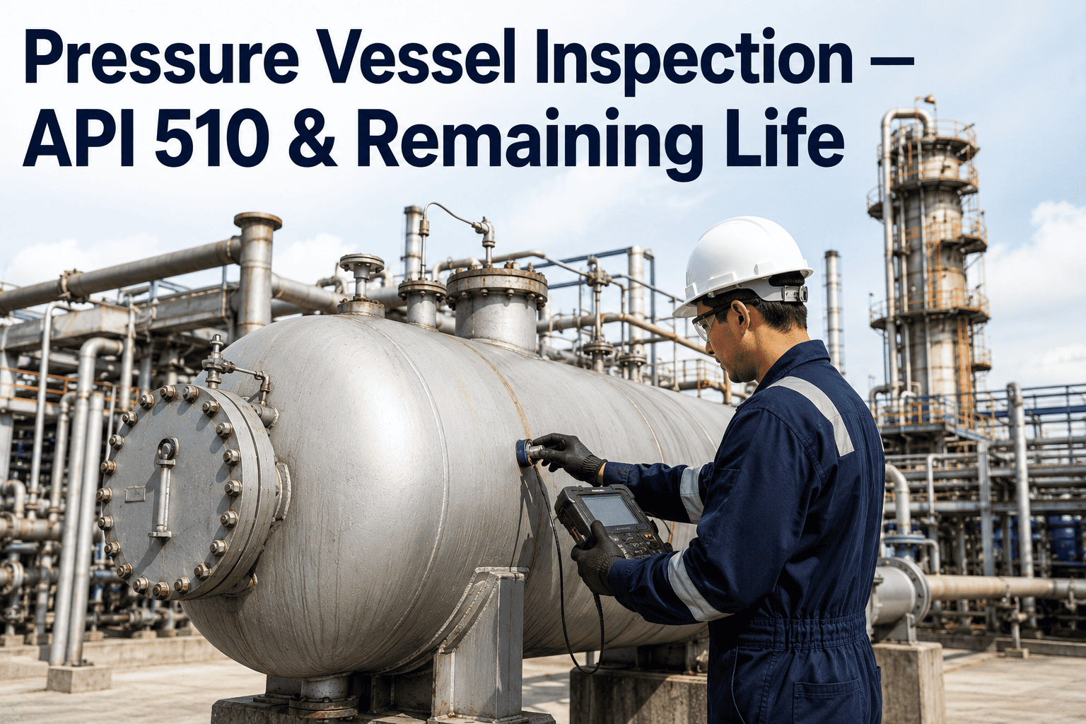
Pressure vessels operate under extreme combinations of pressure, temperature, and corrosive media for decades, and their structural integrity depends entirely on knowing how much metal remains between the internal process and the outside environment. API 510 provides the inspection code that governs how these vessels are examined, how corrosion rates are calculated from thickness data, and how remaining life is determined to set the next inspection date. When a vessel is found with thinning, pitting, or cracking that exceeds standard assessment limits, API 579 fitness-for-service analysis takes over to evaluate whether the vessel can continue operating safely at a reduced pressure or with a repaired condition. Facilities that rely on spreadsheet-based thickness tracking often miss the correlation between damage mechanism activity and inspection findings, which is where a structured data platform changes the outcome. Teams ready to move from reactive vessel inspection to a calculated integrity program can Book a Demo to see how iFactory manages API 510 compliance and remaining life calculations.
Three Standards That Govern Pressure Vessel Integrity
Pressure vessel inspection does not rely on a single standard. The integrity management process draws from three interrelated codes, each serving a distinct purpose. API 510 defines how vessels are inspected and how thickness data is used to set intervals. API 579 provides the analytical methods for evaluating vessels that have damage beyond what API 510 can assess. NBIC governs how repairs and alterations are performed to return a vessel to service. A facility that treats these as separate compliance exercises rather than a connected integrity workflow will always have gaps between inspection findings and the engineering analysis needed to act on them.
API 510 — Vessel Inspection Code
Defines the inspection requirements for pressure vessels in hydrocarbon service, including the methodology for calculating corrosion rates from thickness readings, determining remaining life, establishing maximum allowable working pressure based on current condition, and setting the next inspection interval. Every on-stream and out-of-service inspection, every thickness measurement program, and every interval extension justification traces back to this code.
API 579 — Fitness-for-Service
Provides the engineering assessment methods used when a vessel has damage that exceeds the acceptance criteria in API 510 or the original construction code. Covers assessment of general thinning, local thinning, pitting, cracking, bulging, fire damage, and dent-gouge combinations. Each assessment part includes quantitative methods to evaluate whether the damaged component can continue operating at a specified pressure and temperature for a defined remaining life.
NBIC — Repair and Alteration
Governs how pressure vessel repairs and alterations are designed, performed, inspected, and documented to ensure the repaired vessel meets the applicable code of construction. Covers welding procedures, post-weld heat treatment requirements, pressure testing, and the documentation needed for an authorized inspector to accept the repair. Any vessel that requires a physical repair after an API 510 or API 579 assessment must follow NBIC requirements before returning to service.
Where to Inspect on a Pressure Vessel and What to Look For
A pressure vessel is not a single inspection point — it is a collection of zones, each with different stress states, different exposure to the process, and different vulnerability to specific damage mechanisms. An effective API 510 inspection program examines each zone with the appropriate nondestructive examination technique for the damage mechanisms that are credible in that location. The zone map below shows the standard inspection regions and what each one requires.
Inspection Focus
Internal corrosion at vapor-liquid interface, erosion from inlet nozzles, thermal fatigue at head-to-shell weld, and external corrosion under insulation on the crown.
Inspection Focus
Systematic thickness mapping at grid points to quantify general corrosion, focused inspection at weld seams for cracking, and external inspection at support rings and insulation penetrations where moisture ingress causes under-insulation corrosion.
Inspection Focus
Internal corrosion from settled solids and water accumulation, erosion at outlet nozzles, and external corrosion at the skirt-to-head attachment weld where water can be trapped.
Inspection Focus
Reinforcement pad venting and corrosion under pads, nozzle bore erosion, flange face damage, and cracking at nozzle-to-shell welds from thermal cycling or external loading.
How Corrosion Rate and Thickness Data Determine When a Vessel Needs Its Next Inspection
The remaining life calculation is the central analytical step in every API 510 inspection. It converts thickness measurements and historical corrosion data into a predicted number of years before the vessel reaches its minimum required thickness, which directly determines the inspection interval. The calculation follows a defined sequence from measured data through to the next inspection date.
Determine Actual Thickness
Use the lowest thickness reading from the most recent inspection grid, excluding anomalous readings that have been verified as measurement errors. This becomes the baseline for the remaining life calculation.
Calculate Minimum Required Thickness
Calculated per the original code of construction using current operating pressure, inside radius, allowable stress at design temperature, joint efficiency, and corrosion allowance. This is the thickness below which the vessel cannot operate at its rated MAWP.
Establish Long-Term Corrosion Rate
Use the long-term corrosion rate calculated from the first thickness reading to the most recent reading, not the short-term rate between the last two inspections. The long-term rate smooths out measurement variability and provides a more stable basis for life prediction.
Calculate Remaining Life
Remaining life in years is the thickness above minimum divided by the corrosion rate. If actual thickness is already at or below minimum, remaining life is zero and the vessel requires immediate engineering evaluation before continued operation.
Set Next Inspection Date
API 510 requires the next inspection interval to be set at half the calculated remaining life, capped at the code maximum. This half-life rule ensures the vessel is re-inspected before it consumes more than half of its remaining thickness margin, providing a safety buffer against corrosion rate acceleration.
What Degrades Pressure Vessel Wall Thickness and Structural Integrity
The remaining life calculation assumes a uniform corrosion rate, but real vessels degrade through a combination of mechanisms that affect different zones at different rates. Identifying which mechanisms are active on each vessel is a prerequisite for selecting the right inspection technique and interpreting the thickness data correctly. Missing a credible damage mechanism means the inspection plan will not detect the degradation mode that is most likely to cause failure.
General Corrosion
Uniform metal loss across exposed surfaces driven by process fluid chemistry, most commonly CO2 or H2S in wet gas service and acid or caustic environments in refining. Detected by systematic thickness mapping and tracked through longitudinal thickness trending at fixed grid locations.
Localized Corrosion and Pitting
Concentrated metal loss at specific locations caused by localized chemistry differences, under-deposit attack, or microbiological activity. Pitting is more dangerous than general corrosion because it can penetrate the wall much faster than the average corrosion rate suggests, requiring focused UT or profile radiography.
Hydrogen-Induced Cracking
Stepwise cracking in steels exposed to wet H2S service, where atomic hydrogen enters the metal and recombines at inclusions to form internal cracks. Does not always produce measurable wall thinning, so standard thickness surveys will not detect it. Requires ultrasonic shear wave or phased array examination.
Stress Corrosion Cracking
Cracking driven by the combination of tensile stress, a corrosive environment, and a susceptible material. Sulfide stress cracking in hard welds, chloride stress corrosion cracking in austenitic stainless steel, and caustic cracking in carbon steel are the most common forms in vessel service.
High-Temperature Hydrogen Attack
Decarburization and microfissuring of carbon and low-alloy steels exposed to high-pressure hydrogen at elevated temperatures. Damage is irreversible and progressive, and the affected steel loses both strength and ductility. Assessed using Nelson curves and detected through hardness testing and metallographic examination.
Creep Damage
Time-dependent deformation and grain boundary cavitation in vessels operating above approximately 800 degrees Fahrenheit. Creep is a function of temperature, stress, and time, and it progressively reduces the load-carrying capacity of the material. Monitored through dimensional changes, replica metallography, and creep rupture analysis.
How Wall Thinning Reduces Maximum Allowable Working Pressure
As corrosion reduces the vessel wall from its original thickness to its current thickness, the maximum pressure the vessel can safely contain also decreases. API 510 requires that the MAWP be recalculated at each inspection using the actual measured thickness rather than the original design thickness. If the recalculated MAWP falls below the operating pressure, the vessel must be either derated, repaired, or removed from service. The visual below shows how this relationship works for a typical vessel where thinning has reduced the pressure capacity below the original design rating.
The 40 psi gap between operating pressure and calculated MAWP is the remaining safety buffer. As corrosion continues, this margin shrinks. When it reaches zero, the vessel must be derated or repaired before the next operating cycle.
When API 579 Fitness-for-Service Takes Over from API 510
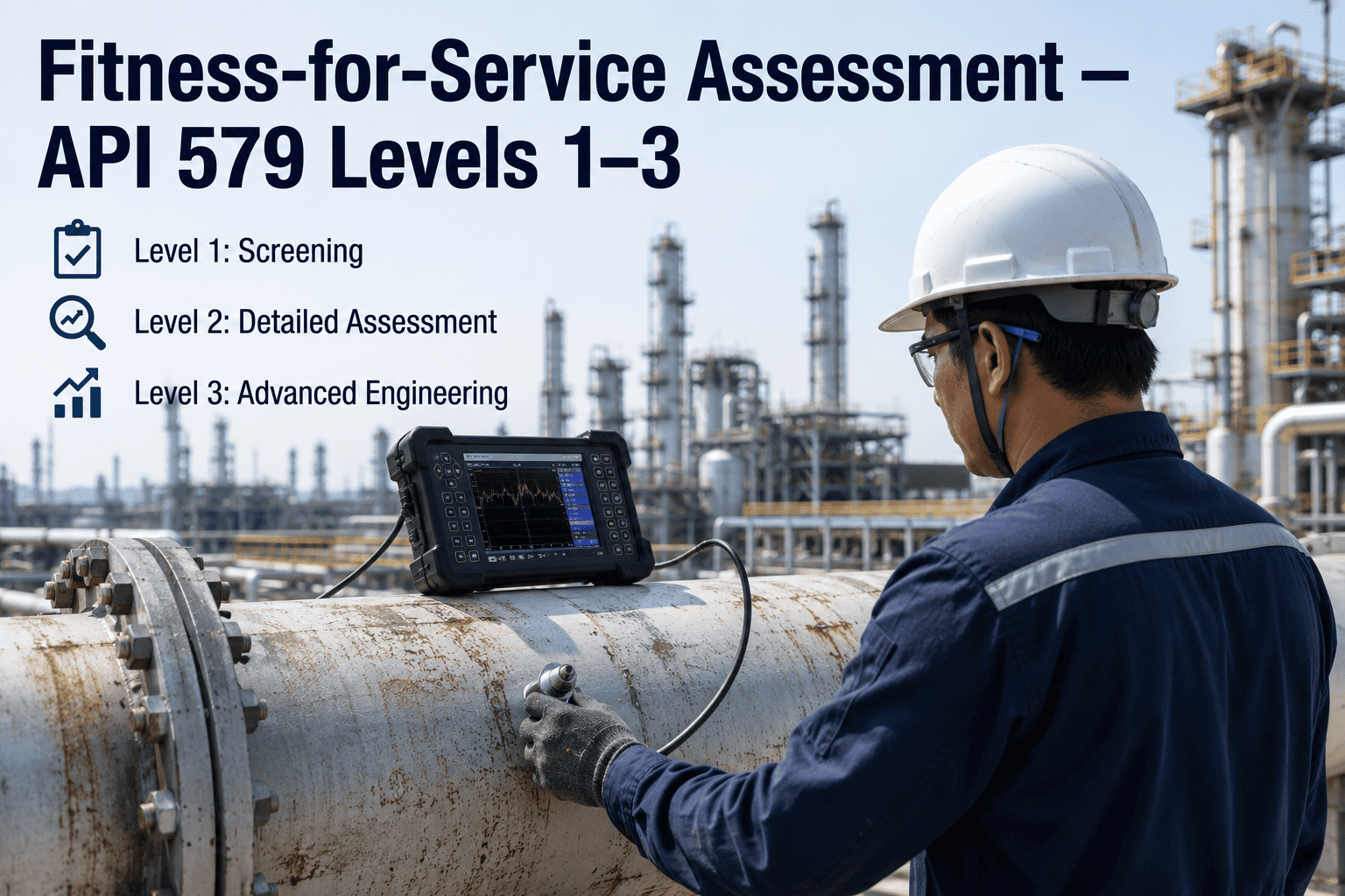
API 510 provides the framework for routine inspection and remaining life calculation based on uniform thinning assumptions. When a vessel has damage that does not fit those assumptions — local thinning that is deeper than the surrounding area, pitting clusters, cracks detected during examination, or distortions from fire or mechanical loading — API 510 reaches its analytical limits. API 579 fitness-for-service provides the next level of engineering assessment, with three levels of increasing analytical rigor that match the complexity of the damage and the criticality of the vessel.
Screening Assessment
Conservative point-by-point evaluation using simplified formulas. Each damaged location is assessed independently against allowable flaw sizes. Fastest to perform but produces the most conservative results, often requiring unnecessary repairs or derating because it does not account for the structural interaction between adjacent damaged regions or the residual strength of the surrounding sound material.
Detailed Assessment
Uses the actual damage profile — including the length, width, and depth of the thinned or damaged region — to calculate the remaining strength factor. Accounts for the interaction between adjacent flaws and the reinforcement effect of surrounding undamaged material. Produces less conservative results than Level 1 and is the most commonly used assessment level for local thinning, pitting, and crack-like flaws in pressure vessel service.
Advanced Analysis
Full numerical analysis using finite element modeling to evaluate complex damage configurations, combined loading, and interaction between multiple damage types that Level 2 methods cannot address. Required when the damage geometry falls outside the validated ranges of the Level 2 procedures, when multiple damage mechanisms overlap, or when the vessel operates in a high-consequence service where a more precise failure prediction is justified by the risk reduction benefit.
Pressure Vessel Inspection and Remaining Life — Common Questions
How often must pressure vessels be inspected under API 510?
API 510 establishes the maximum interval between inspections at half the calculated remaining life or ten years, whichever is shorter. However, the actual interval is determined by the inspection engineer based on the vessel condition, corrosion rate, operating severity, and damage mechanism activity. Many facilities set internal targets more aggressive than the code maximum to provide additional margin, particularly for vessels in high-consequence services or those with active damage mechanisms that could accelerate unexpectedly. The interval can also be shortened if operating conditions change, if inspection findings indicate faster-than-expected corrosion, or if a process upset has potentially damaged the vessel. Teams that manage intervals through a structured data system rather than manual calendars can adjust inspection timing dynamically as new thickness data becomes available. Book a Demo to see how iFactory automates interval calculations based on live thickness data.
What happens if an inspection reveals the vessel is below minimum thickness?
When the actual thickness at any measurement point falls at or below the calculated minimum required thickness, the vessel cannot continue operating at its current MAWP without further engineering evaluation. The immediate options are to reduce the operating pressure to a level that the remaining thickness can support, which requires a formal MAWP recalculation and rerating documentation, or to remove the vessel from service for repair or replacement. If the thinning is localized rather than general, an API 579 fitness-for-service assessment may demonstrate that the vessel can continue operating at a specified pressure for a defined period even with the local thinning present, provided the assessment shows the remaining strength factor is above the acceptance criterion. The iFactory Support team can advise on how the platform captures below-threshold findings and triggers the appropriate evaluation workflow.
When is an API 579 assessment required instead of a standard API 510 evaluation?
API 579 is required whenever the vessel has damage that falls outside the acceptance criteria defined in API 510 or the original construction code. This includes localized thinning where the minimum thickness in a damaged area is below the uniform corrosion allowance, pitting where the pit depth exceeds the threshold for standard assessment, crack-like flaws detected by magnetic particle, penetrant, or ultrasonic examination, and distortions from fire exposure, mechanical impact, or foundation settlement. API 510 can handle uniform thinning where the thickness is above minimum across the entire vessel, but it does not provide analytical methods for evaluating the structural significance of localized damage. Attempting to use API 510 methods for damage that requires API 579 analysis will either produce an overly conservative result that forces unnecessary repair or an invalid result that does not meet code requirements.
How is the long-term corrosion rate different from the short-term rate and which should be used?
The short-term corrosion rate is calculated from the two most recent thickness readings, while the long-term rate is calculated from the first reading on record to the most recent reading. The long-term rate is the preferred basis for remaining life calculation because it averages out the measurement variability, instrument differences, and temporary process upsets that can make the short-term rate appear artificially high or low. A vessel that shows a short-term rate of 20 mils per year based on the last two inspections but a long-term rate of 8 mils per year over ten years of data is almost certainly experiencing measurement scatter rather than a true acceleration in corrosion. API 510 allows use of the short-term rate only when it is demonstrably higher than the long-term rate and there is a documented technical reason to believe the corrosion mechanism has changed, such as a known process chemistry shift or a new upstream contamination source.
Can a vessel be rerated to a lower MAWP instead of being repaired or replaced?
Yes, rerating is a code-acceptable alternative to repair or replacement when the vessel's current thickness can support a lower pressure that still meets process requirements. The rerating calculation uses the same code formulas as the original design but substitutes the actual measured thickness for the original thickness. The rerating must be documented on a formal rerating record, reviewed and approved by an authorized inspector, and the vessel nameplate must be updated or a supplemental nameplate installed to reflect the new MAWP and any associated temperature limitations. The critical consideration is whether the lower pressure still allows the vessel to perform its function in the process — if the vessel is a reflux drum that operates at 50 psi and the rerated MAWP is 200 psi, the rerating has no operational impact. If the vessel is a high-pressure separator that must operate at 1,200 psi and the rerated MAWP is 900 psi, the rerating is not viable and repair or replacement becomes necessary.