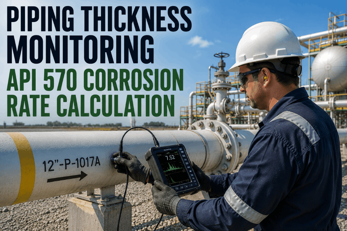
A process unit can have tens of thousands of feet of piping and only a few hundred points where anyone actually measures wall thickness — which means the entire integrity picture for that unit rests on whether those few hundred points were chosen well. API 570 doesn't ask inspectors to check everything; it asks them to concentrate inspection effort on condition monitoring locations that represent where corrosion actually concentrates, then trend thickness at those exact points across every future inspection cycle. Get the CML selection wrong, or lose the historical record connecting decades of readings at the same physical spot, and even a rigorous inspection program ends up flying mostly blind. For piping engineers and inspection planners managing circuits across an aging asset base, CML management is where the real integrity work happens. Contact our support team to see how CML history consolidation applies to your circuit inventory.
Not All Piping Gets Inspected the Same Way
API 570 sorts every circuit into one of three risk classes based on what it carries and at what pressure, and that classification drives how often it needs to be inspected — treating a low-pressure utility line the same as a high-pressure sour service circuit wastes inspection resources in one place while under-protecting the other. Getting this classification right at the outset shapes everything downstream — how many CMLs a circuit needs, how tight its inspection interval can be, and how much scrutiny a single anomalous reading deserves before it triggers a follow-up inspection.
| Risk Class | Typical Service | Max External Interval | Inspection Emphasis |
|---|---|---|---|
| Class 1 | Flammable, toxic, or high-consequence fluids at elevated pressure | 5 years, sooner if corrosion rate dictates | Highest CML density; tightest corrosion rate tolerance |
| Class 2 | Moderate-hazard process fluids at intermediate pressure | 10 years, sooner if corrosion rate dictates | Moderate CML density; standard corrosion circuit review |
| Class 3 | Low-pressure, non-hazardous or utility services | 10 years, often extended further with strong data history | Lowest CML density; corrosion typically slow and predictable |
What Actually Determines Where a CML Belongs
Choosing CML locations is a judgment call that balances data confidence against practical inspection effort, and a handful of factors consistently drive where the highest-value locations sit on any given circuit.
None of these factors work in isolation — a circuit often combines two or three of them, such as a dead leg that is also insulated and sitting near a soil-air interface, and that combination is exactly where the highest-consequence failures tend to originate. Experienced inspectors build a mental map of these overlapping risk factors for every circuit they manage, but that map is only as good as the documentation behind it, and it rarely survives a change in personnel unless it's captured in a structured, circuit-by-circuit record rather than institutional memory.
Long-Term vs. Short-Term Corrosion Rate — Why Both Matter
Every CML with enough measurement history supports two separate corrosion rate calculations, and API 570 requires the more conservative of the two to govern the next inspection interval and remaining-life calculation.
Calculated across the full measurement history from the earliest reliable reading to the most recent one. LTCR smooths out any single anomalous reading and reflects the circuit's overall corrosion behavior across its service life, but it can understate a recent acceleration in corrosion rate if the process conditions have changed.
Calculated from only the two most recent readings, STCR is far more sensitive to a recent change — a process upset, a chemical injection change, or a new corrosion mechanism taking hold. When STCR diverges significantly from LTCR, that divergence itself is often the earliest signal that something on the circuit has changed and deserves investigation.
Running both calculations automatically every time a new reading comes in, and flagging any meaningful divergence between them, is what separates a piping integrity program that catches an emerging problem early from one that only reacts once a circuit is already close to its retirement thickness. Book a demo to see how this comparison runs against your own circuit history.
The practical challenge is that both calculations depend entirely on having clean, comparable readings tied to the exact same CML across every inspection cycle. A corrosion rate calculated from two readings taken at slightly different points along a weld seam, or measured with different instrument calibration standards, can produce a number that looks precise but doesn't actually reflect real metal loss — and a false corrosion rate is often worse than no corrosion rate at all, because it creates unwarranted confidence in either direction. This is exactly why CML documentation — recording the precise location, orientation, and measurement method for every point — matters just as much as the thickness reading itself. A well-documented CML with a decade of consistent readings will always produce a more trustworthy corrosion rate than a poorly documented one with twice as many data points spread across inconsistent locations.
The Cost of Getting CML Management Wrong
Every gap below sounds small in isolation, but each one directly undermines the corrosion rate calculation that everything else in a piping integrity program depends on, and the four gaps below tend to show up together at facilities that have never consolidated their inspection history into one system.
| Gap | Consequence | What Consolidated CML Data Fixes |
|---|---|---|
| CML locations drift between inspection cycles | Corrosion rate calculated from readings that aren't actually the same physical spot | Fixed CML registry with mapped coordinates ensures every cycle measures the same point |
| Inspection history split across contractors | Conservative default corrosion rate assumptions used in place of real trend data | Full multi-cycle history consolidated per CML regardless of which contractor collected it |
| High-risk CMLs under-monitored | Localized corrosion at dead legs or CUI zones missed until a leak occurs | Damage-mechanism-aware CML placement reviewed against actual circuit geometry |
| Manual re-inspection date tracking | Circuits inspected later than the code-required interval, or inspected needlessly early | Automated re-inspection date calculated per circuit from the governing corrosion rate |
Prioritizing Which Circuits Get Attention First
Most facilities don't have the inspection resources to treat every circuit with equal urgency, and they shouldn't — risk-based inspection methodology exists specifically to concentrate effort where the combination of failure probability and failure consequence is highest, rather than spreading inspection budget evenly across a circuit inventory where the real risk is heavily concentrated in a small subset of circuits. A circuit carrying a mild, well-understood corrosion mechanism at low pressure in a non-critical unit simply doesn't need the same inspection intensity as a high-pressure, high-temperature circuit in sour or wet H2S service running through a congested pipe rack above a control room. Building this prioritization on paper, based on process knowledge and damage mechanism review, is the starting point — but the ranking only stays accurate if it's continuously updated as new thickness readings, process changes, or metallurgical upgrades come in.
This is where risk-based inspection and CML management genuinely depend on each other. A circuit's risk ranking should influence how many CMLs it gets and how tight the inspection interval is, but the CML data itself — the actual measured corrosion rate — should also feed back into and refine that risk ranking over time. A circuit initially assumed to be moderate risk that turns out to be corroding faster than expected needs its risk classification revisited, not just its next inspection date recalculated. Facilities that keep these two processes connected, rather than running risk ranking as a one-time exercise and CML tracking as a separate ongoing activity, end up with an inspection program that actually reflects current circuit condition rather than an assumption made years earlier at the last formal risk assessment.
A Piping Inspection Planner's Take on CML Discipline
Twelve years into planning piping inspection programs across multiple process units, the pattern I see over and over is that facilities have plenty of thickness readings — what they don't have is confidence that those readings are actually comparable to each other. I inherited a unit where three different inspection contractors had each used slightly different CML numbering conventions over fifteen years, and reconciling which reading belonged to which physical location took us most of a turnaround planning cycle. Once we rebuilt the CML registry with fixed coordinates and mapped every historical reading back to the correct point, we found two circuits where the real corrosion rate was almost double what the previous conservative estimate assumed, and one where it was actually much lower than assumed, meaning we had been over-inspecting a perfectly healthy circuit for years. Getting the CML data right isn't a paperwork exercise — it directly changes which circuits you inspect sooner and which ones you can safely leave alone longer.
Frequently Asked Questions — API 570 Piping Inspection and CML Management
There's no fixed number — API 570 leaves CML density to inspector judgment based on how uniform or localized the expected corrosion mechanism is. A circuit with slow, uniform general corrosion might reasonably be monitored with just a handful of CMLs, since thickness loss should behave similarly anywhere along the circuit. A circuit exposed to localized mechanisms like erosion-corrosion at elbows, under-deposit corrosion at low points, or corrosion under insulation needs meaningfully more CMLs, placed specifically at the locations where those mechanisms are known to concentrate. The right number is really a function of desired confidence in the resulting corrosion rate, balanced against the practical cost of collecting and maintaining that many data points every inspection cycle.
API 570 requires the more conservative of the two rates to govern the next inspection interval and remaining-life calculation, so a significant divergence automatically tightens the inspection schedule for that circuit rather than being averaged away. Beyond the code requirement, a meaningful STCR-LTCR divergence is itself valuable diagnostic information — it usually means something changed in the operating conditions, chemical treatment program, or process chemistry recently enough that the long-term average hasn't caught up yet. Investigating what changed around the time the divergence appeared often identifies the root cause faster than waiting for the next scheduled inspection to confirm the trend.
Yes, though it takes deliberate reconciliation work rather than simply merging spreadsheets. The key is mapping each contractor's historical readings back to a single, fixed CML registry using location coordinates, isometric drawing references, or physical markers rather than relying on numbering conventions that may differ between contractors. Once that reconciliation is done, the full multi-decade history becomes usable for corrosion rate calculation instead of being treated as several shorter, disconnected data sets. Reach out to support if you're working through this kind of historical reconciliation on your own circuit inventory.
Small-bore connections are frequently under-represented in CML programs relative to how often they actually appear in piping failure and leak history, largely because they're easy to overlook next to the main run of a circuit. Vent, drain, and instrument connections see different flow conditions than the main line, can be points of vibration fatigue in addition to corrosion, and are often installed with thinner wall schedules that leave less margin before reaching a retirement thickness. Including representative small-bore connections in the CML program, rather than assuming the main circuit's corrosion behavior applies equally to every branch, closes a gap that shows up disproportionately often in incident investigations.
Computed re-inspection due dates, generated automatically from each circuit's governing corrosion rate, feed directly into work orders inside the CMMS and EAM platforms your planning team already uses, and are cross-referenced against upcoming turnaround planning calendars so inspection scope can be bundled into already-scheduled outages wherever possible. For circuits showing sustained thinning, updated maximum allowable working pressure calculations support fitness-for-service decisions between scheduled inspections, giving planners a documented basis for either continuing operation or advancing a repair. Book a demo to see this workflow set up against your own circuit inventory.