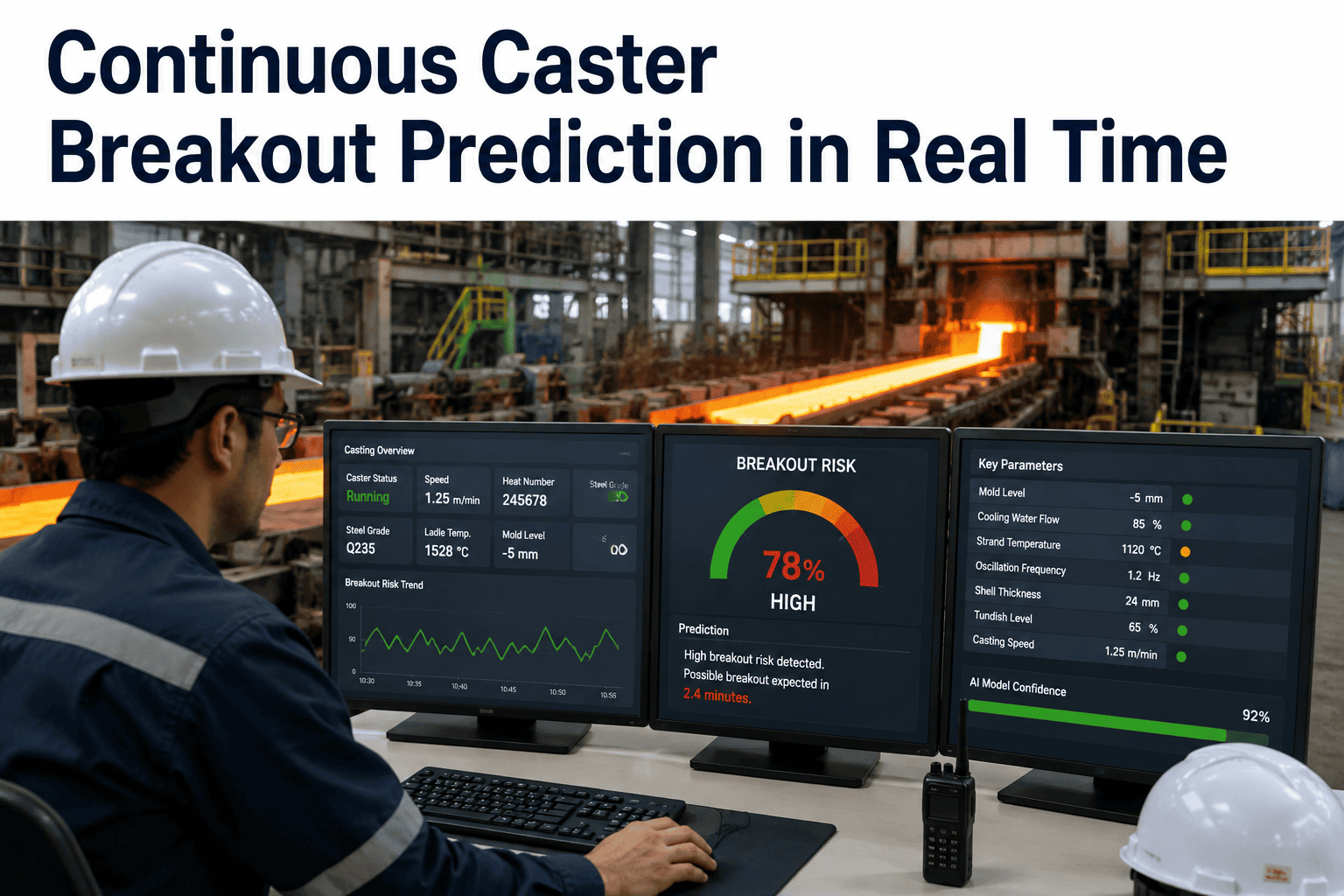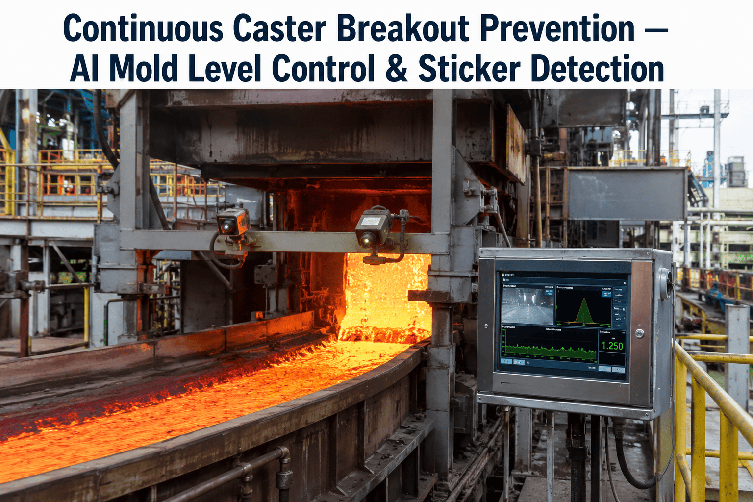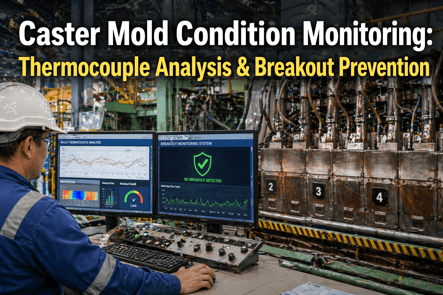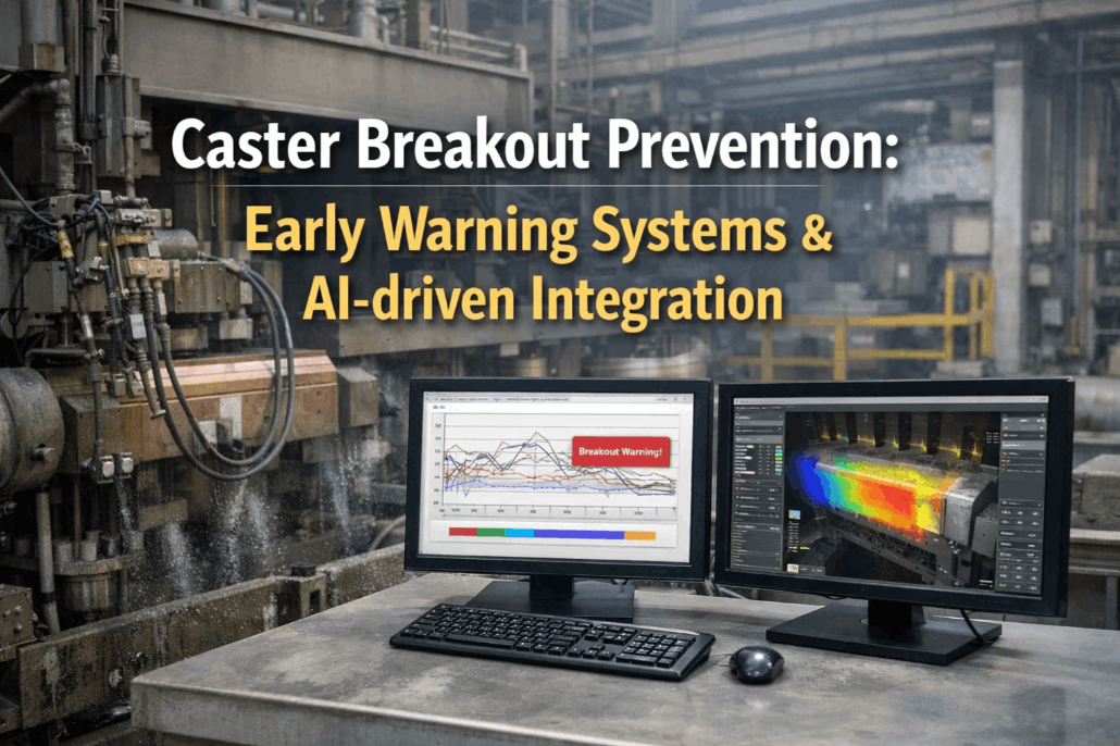
By the time a breakout alarm actually sounds, the shell has already torn. Every breakout prediction system installed at a modern caster is really racing a clock that started the moment a sticker began forming, somewhere between the meniscus and the mold exit, minutes before any operator could see it happening. Thermocouple arrays catch the thermal signature of that tear as it propagates, but only after the shell has already thinned dangerously in that spot, which means the alarm is a warning about damage already underway, not a measurement of shell health before the problem starts. iFactory's shell thickness module exists to close that gap, estimating shell condition continuously instead of waiting for a thermal signature to confirm a defect already forming.
Thermocouples confirm a sticker after it starts. Shell thickness monitoring sees it coming.
iFactory infers real-time shell thickness from your existing mold thermocouples and cooling water data, giving operators minutes of lead time before a thermal signature would ever trigger a traditional alarm.
The five stages a breakout goes through before anyone sees it
A sticker-type breakout follows a recognizable thermal progression, but each stage compresses into a matter of minutes, which is why catching it early depends on watching the pattern take shape rather than waiting for it to fully develop.
Lubrication gap forms
Mold powder film distributes unevenly, leaving a small area where the shell adheres directly to the copper wall instead of sliding freely.
Shell tears at the stick point
As the strand continues moving, the adhered shell tears, opening a thin spot that molten steel begins pressing against from inside.
Upper thermocouple spikes
The thin spot passes the upper sensor row, registering a sharp temperature rise as hotter steel sits closer to the mold wall.
Pattern propagates downward
The same thermal spike appears sequentially in lower thermocouple rows as the thinned shell area moves down with the strand.
Shell exits critically thin
Without intervention, the thinned shell exits the mold with insufficient thickness to contain ferrostatic pressure, and ruptures.
Traditional breakout detection systems are built to catch stage three and four, the sequential temperature rise across thermocouple rows. That's a real signal, but it only appears after the shell has already thinned enough to change local heat transfer meaningfully. The earlier stages, where lubrication first becomes uneven, produce a much subtler signature that a threshold-based alarm typically isn't sensitive enough to catch.
Threshold-Based Detection
- Waits for temperature spike to cross a fixed alarm threshold
- Only reliable once shell has already thinned significantly
- Missing or degraded thermocouples create blind spots directly
- High false alarm rate forces conservative, late-triggering thresholds
- No visibility into shell condition when temperatures look normal
iFactory Shell Thickness Estimation
- Continuously estimates shell thickness across the full mold, not just alarm points
- Flags gradual thinning trends before a threshold would ever trigger
- Cross-references thermocouple and cooling water data to fill sensor gaps
- Lower false alarm rate allows earlier, more sensitive intervention
- Gives operators a live shell health view, not just a binary alarm
The instrumented mold already has more data than it's using
Most modern casters already run a densely instrumented mold, often with dozens of thermocouples per plate, feeding a logic-based or early machine-learning breakout prediction system. That data is genuinely valuable, but most existing systems use it narrowly, comparing paired sensor readings against fixed thresholds or known temperature-inversion patterns rather than building a continuous estimate of shell thickness across the whole mold surface.
The gap matters because a caster running with even a modest percentage of failed or degraded thermocouples loses proportionally more breakout detection coverage than the sensor count alone would suggest, since a single dead sensor pair removes an entire monitoring point rather than just slightly degrading accuracy. Combining thermocouple readings with mold cooling water inlet and outlet temperature differential, which most casters already measure to compute heat flux, lets a shell thickness model cross-check and interpolate across those gaps instead of losing coverage entirely when a sensor fails.
There's also a tuning problem specific to logic-based systems. Breakout detection thresholds are typically tuned once, often during commissioning or after a significant breakout event, and rarely revisited as casting speed ranges, mold powder formulations, or steel grades change. A threshold tuned conservatively enough to avoid false alarms on one grade can be too slow to catch a genuine early-stage sticker on a different, faster-casting grade, which is exactly the kind of gap a continuously-calibrated model closes automatically.
Most caster teams have never actually seen what shell thickness looks like across the full mold width in real time, only at the alarm points. Book a walkthrough and we'll show you that view using your own thermocouple data.
From raw sensor data to a shell health view
Ingest thermocouple and cooling data
Reads existing mold thermocouple arrays and cooling water flow and temperature data without new instrumentation.
Build a live heat flux map
Cross-references sensor readings across the mold to estimate local heat transfer at each point along the strand.
Infer shell thickness continuously
Translates the heat flux map into an estimated shell thickness profile updated continuously as casting proceeds.
Flag gradual thinning trends
Surfaces areas trending toward critical thinness well before a threshold-based alarm would trigger.
Recommend speed or intervention
Suggests casting speed reduction or operator inspection specifically where and when risk is rising.
Log and improve
Every event, caught or missed, refines the model's sensitivity for your specific mold geometry and grade mix.
Where each approach actually catches a problem
| Method | What it detects | Typical lead time | Blind spot risk |
|---|---|---|---|
| Fixed PLC alarm | Temperature crossing a hard threshold | Seconds to under a minute | High, single-sensor dependent |
| Logic-based pair detection | Sequential temperature rise across sensor rows | 1-3 minutes | Moderate, needs healthy sensor pairs |
| Machine learning classifiers | Learned thermal signatures across broader patterns | 2-5 minutes | Lower, but degrades with sensor failures |
| iFactory shell thickness estimate | Gradual thinning trend across the full mold | 4-12 minutes | Low, interpolates across sensor gaps |
Find your caster's current breakout detection blind spots
We'll audit your thermocouple health and show you where coverage gaps exist right now.
Shell thickness data has value even on strands that never break out
Most heats never come close to a breakout, but shell thickness variability still matters on those heats too, because it correlates with subsurface quality issues like pinholes, off-corner cracks, and inconsistent as-cast structure. A continuous shell thickness estimate gives quality teams a new signal to correlate against downstream surface inspection results, often revealing that certain mold powder practices or casting speed ranges are producing thinner-than-optimal shells well before those conditions ever approach breakout risk.
There's also a maintenance planning benefit that compounds over time. Mold copper wear, taper degradation, and cooling channel fouling all show up first as subtle shifts in the shell thickness pattern before they become severe enough to threaten a breakout directly. Tracking shell thickness trends across a mold's service life gives maintenance teams a much earlier, data-backed signal for when a mold plate should be scheduled for resurfacing or replacement, rather than relying on a fixed campaign length or waiting for a near-miss event to trigger inspection.
Casting speed optimization is another place this data pays off in a way that's easy to overlook. Many casters run below their theoretical maximum speed on certain grades specifically because operators are being appropriately cautious about breakout risk without having a precise, real-time view of actual shell margin. A continuous shell thickness estimate can show, grade by grade, how much genuine margin exists at current operating speeds, sometimes revealing that a conservative speed limit set years ago has more headroom than anyone realized, and other times confirming that a limit assumed to be conservative is actually appropriately tight. Either answer is useful, and neither is available from a threshold-based alarm that only ever reports pass or fail.
The math behind a shell monitoring pilot is unusually simple
Most AI pilots in a steel plant require some estimation to build a business case, projecting savings against assumptions that are hard to verify until the system has run for months. Shell thickness monitoring is different because the primary benefit, avoided breakouts, is one of the few events in a melt shop with a well-documented, largely undisputed direct cost. A plant that has experienced even a handful of breakout events in recent years typically already has the cost data needed to build a defensible return calculation before the pilot even starts, since direct losses per event are usually well tracked by maintenance and operations reporting.
The indirect costs are worth including as well, even though they're harder to quantify precisely. A breakout doesn't just damage the strand and consume repair time, it typically forces an extended caster outage for segment and roll inspection afterward, disrupts scheduling for downstream rolling operations waiting on that caster's output, and in more severe cases creates safety incidents that trigger broader operational reviews. Teams building the case for a shell thickness pilot often find that when these secondary costs are included honestly, the payback period shortens considerably compared to counting direct breakout costs alone.
Because the pilot uses instrumentation already installed, there's also no meaningful capital outlay competing with the return calculation, which tends to make this one of the more straightforward approvals for a caster team pursuing its first AI-assisted safety project. Many teams that start here later use the pilot's clear ROI story to build internal support for extending predictive monitoring to other safety-critical equipment across the plant.
What a shell thickness pilot involves
No new sensors required
Works with the thermocouple array and cooling water instrumentation already installed on your mold.
Runs alongside existing breakout systems
Adds a continuous shell thickness layer without replacing your current logic-based or PLC alarm system.
Calibrated on historical events
Uses past breakout and near-miss records to validate model sensitivity before going live.
Shadow mode first
Runs in parallel with existing alarms, comparing detection timing before operators act on new alerts.
Grade and section flexible
Calibrates separately for billet, bloom, and slab geometries and different grade families.
On-premise deployment
Runs on an NVIDIA appliance inside your plant network for real-time response with no cloud dependency.
Shell thickness monitoring, explained plainly
See shell thickness before a thermal alarm ever would
iFactory turns the mold instrumentation you already have into a continuous shell health view. Book a demo and we'll show you what it reveals in your own casting data.