Computer vision is redefining quality control in steel manufacturing. Where human inspectors catch 60–70% of surface defects under ideal conditions, AI-powered vision systems achieve 99.7% detection accuracy — at full line speed, around the clock, without fatigue. The global machine vision market in metals is growing at 14.3% CAGR and is projected to reach $3.8 billion by 2030, driven by zero-defect manufacturing mandates from automotive, aerospace, and construction customers. From continuous casting slabs to hot-rolled coils, cold-rolled sheets, coated products, and tube and pipe — computer vision systems now inspect every stage of the steel production chain with sub-millimetre precision. iFactory's AI manufacturing platform integrates computer vision inspection directly into your production workflow, connecting defect data to process controls quality records, and customer documentation. Book your free demo and see how AI vision transforms your quality operation.
Computer Vision for Steel Defect Detection:
From Slabs to Finished Products
Human inspectors miss 30–40% of surface defects. AI vision systems catch 99.7% — at full line speed, on every shift, without fatigue. Here's how computer vision is transforming steel quality from casting to dispatch.
Steel Defect Types Computer Vision Identifies
Modern AI vision systems classify defects by type, severity, size, and location — providing root-cause data that guides process corrections upstream.
- Scale Iron oxide patches from hot rolling — detected by texture contrast algorithms
- Cracks Longitudinal, transverse, and edge cracks — sub-0.1mm width detection
- Slivers Thin metallic protrusions from casting inclusions — high-risk in pressure vessels
- Pits & Pinholes Surface depressions from oxide inclusions or roll damage
- Rolled-In Scale Scale embedded during rolling — causes coating adhesion failures
- Gouges & Scratches Mechanical damage from guides, table rolls, or coil handling equipment
- Edge Waviness Undulating strip edges from uneven rolling pressure — causes downstream forming issues
- Camber Lateral curvature along strip length — detected by laser profilometry + vision
- Thickness Variation Cross-profile and longitudinal thickness deviations beyond tolerance
- Width Deviation Strip width outside specification — detected in real time by edge detection
- Flatness Defects Centre buckles, edge waves, and quarter buckles — mapped by 3D vision
- Coil Set / Crossbow Residual curvature after coiling — measured by laser triangulation sensors
- Internal Cracks Solidification cracks from casting — detected by ultrasonic arrays with AI analysis
- Inclusions Non-metallic slag or oxide inclusions — UT + eddy current + vision combined
- Porosity Gas voids from solidification — impacts mechanical properties, detected by UT
- Segregation Compositional variation from solidification — correlates with surface banding
- Laminations Internal separations from inclusion stringers — critical for pressure applications
- Pipe & Shrinkage Central voids in billets/blooms — eliminated by crop optimization AI
- Bare Spots Missing zinc or paint coating — detected by fluorescence or reflectance sensors
- Coating Thickness Variation Uneven galvanizing detected by X-ray fluorescence + vision mapping
- Dross Inclusions Zinc dross particles embedded in coating — causes paint adhesion failure
- Spangle Irregularity Uneven crystallization pattern on galvanized sheet — visual quality issue
- Orange Peel Surface texture defect in cold-rolled or pre-painted products
- Rust Staining Corrosion spots from moisture during storage — colour anomaly detection
Computer Vision Inspection: Slab to Finished Product
Each production stage has unique defect signatures, line speeds, temperatures, and inspection challenges. AI vision systems are engineered for the specific conditions at each point.
Continuous Cast Slabs & Billets
Hot surface inspection at 800–1,100°C using thermal and near-infrared cameras. Detects longitudinal cracks, transverse cracks, and corner defects before scarfing. AI analysis determines crop lengths to eliminate shrinkage pipe. Early defect detection at this stage prevents defects from propagating through the entire rolling campaign.
Hot Strip Mill
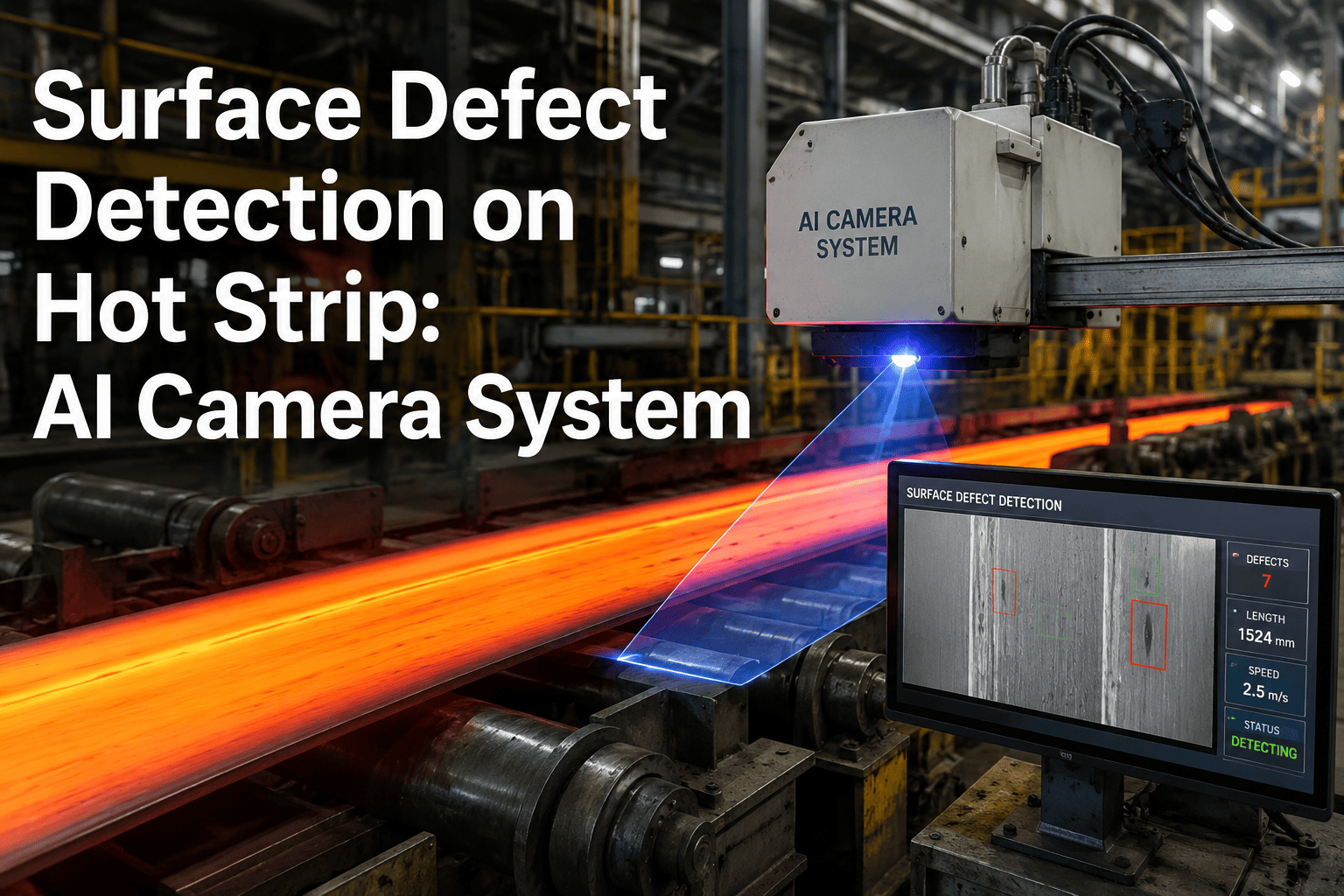
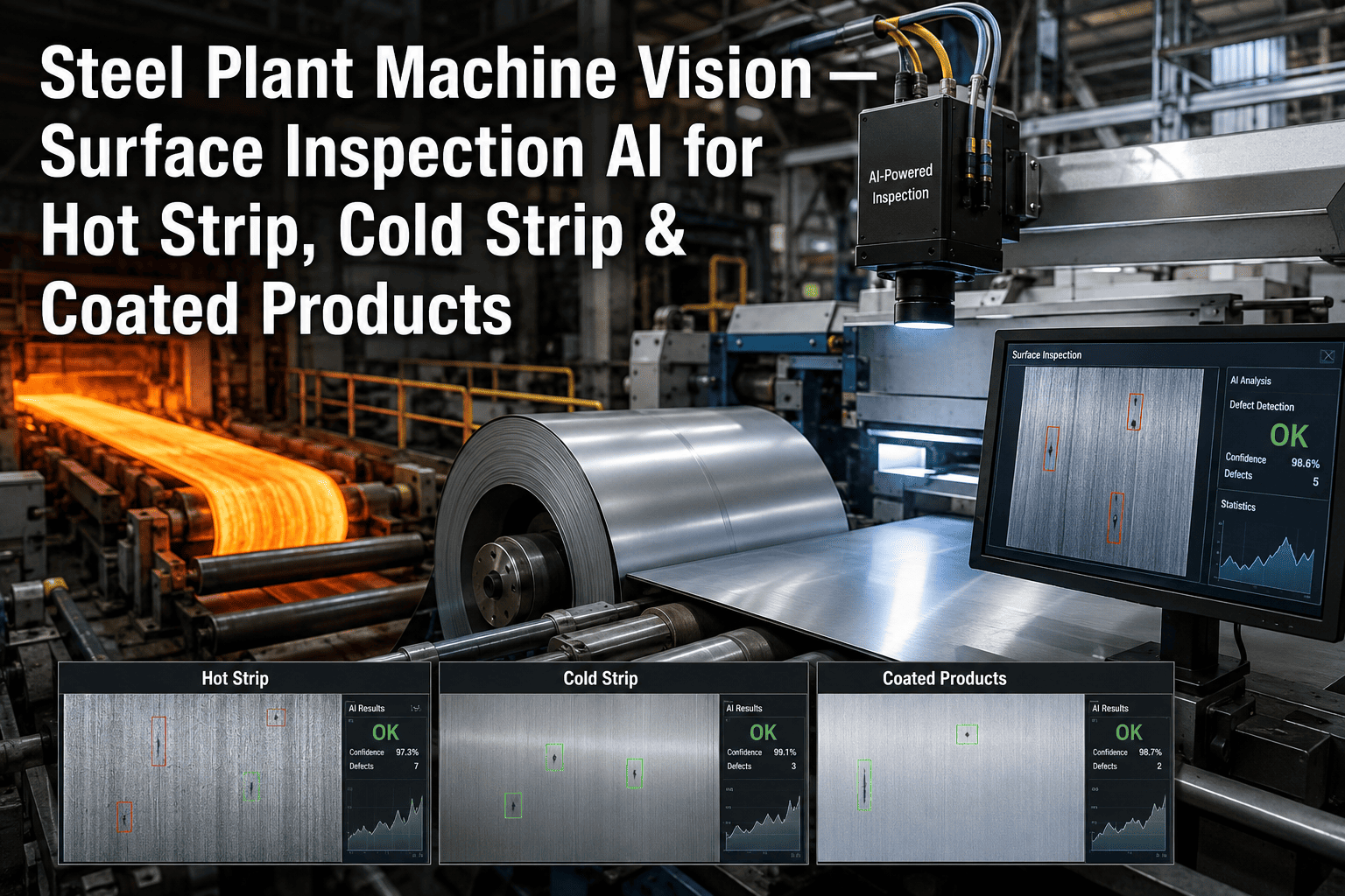
Vision systems mounted at the exit of the finishing mill inspect at speeds up to 20 m/s and strip temperatures of 600–900°C. Line-scan cameras with high frame rates capture scale, cracks, rolled-in scale, and surface marks across the full strip width. Real-time classification triggers automatic marking and downstream sorting decisions.
Cold Rolling Mill
Room-temperature inspection at speeds up to 30 m/s on polished or pickled surfaces. High-resolution line-scan cameras detect fine cracks, slivers, seams, and mechanical damage invisible on hot-rolled material. Edge inspection cameras monitor for edge cracks that indicate rolling instability. Thickness and flatness sensors integrated into the same platform.
Galvanizing & Coating Lines
Dual-surface inspection of zinc-coated, aluminized, and pre-painted products. Fluorescence sensors detect bare spots where coating is absent. Reflectance mapping identifies coating thickness variation, dross inclusions, and spangle irregularity. Paint line inspection catches orange peel, colour deviation, and surface blemishes in top-coat and primer layers.
Plate Mill
Large-format plates (up to 5m wide) inspected by multi-camera arrays covering the full surface. Vision systems operate after the plate cooling bed and before ultrasonic testing. Flatness measurement uses laser profilometry to map the entire plate surface. Crop optimization AI maximizes usable area from defect maps. Plate marking systems tag defect locations for mill records.
Tube & Pipe
Rotating inspection heads or fixed camera arrays with product rotation inspect the full circumference of tubes and pipes. Weld seam inspection uses vision and eddy current combined to detect weld defects, undercut, and porosity. End-face inspection cameras check for laminations, wall thickness deviations, and dimensional conformance at pipe ends.
The AI Vision Inspection Pipeline
From raw image capture to quality record and process feedback — five steps that happen in milliseconds, every metre of steel produced.
Image Capture
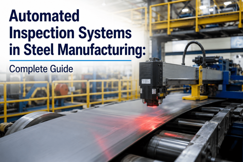
High-speed line-scan or area-scan cameras capture every square centimetre of the steel surface. Structured LED lighting in brightfield, darkfield, and oblique configurations is selected for the defect types targeted. For hot material, thermal and NIR cameras replace visible-spectrum sensors. Frame rates up to 100,000 lines/second ensure no surface is missed at maximum line speed.
Edge AI Processing
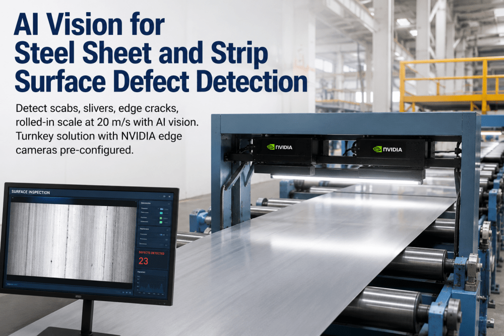
Images are processed by GPU-accelerated edge computing nodes mounted in the production environment. Deep learning models — typically convolutional neural networks trained on millions of labelled steel defect images — classify anomalies in under 5 milliseconds. Edge processing keeps latency low enough for real-time rejection or marking decisions. No cloud round-trip required for line control.
Defect Classification & Grading
Each detected anomaly is classified by type, severity grade, dimensions (length, width, area), and position on the product (distance from edge, longitudinal position). AI models assign a quality grade to each coil, plate, or tube section in real time. Defect maps are generated showing the location and density of every detected anomaly — stored as part of the product quality record.
Automated Decision & Action
Based on configurable quality acceptance criteria by customer and grade, the system automatically triggers: accept and pass, hold for human review, divert to downgrade, or trigger immediate line stop for critical defects. Automatic spray markers or inkjet printers tag defect locations on the product for downstream reference. Rejection decisions are logged with defect images and classification data.
Process Feedback & Quality Records
Defect data is fed back to upstream process controls — rising crack rates trigger alerts to casting operators; increasing scale defects prompt HVAC system adjustments in the reheat furnace. Full quality records link defect maps to mill certificates, customer orders, and heat data. Integration with iFactory provides unified quality dashboards and automated non-conformance reports. See the full platform →
Manual Inspection vs. AI Vision Inspection
Traditional Quality Control
- ✕60–70% defect detection — misses subtle surface flaws
- ✕Inconsistent — inspector fatigue, lighting variation, shift changes
- ✕Sampling-based — only a fraction of output is inspected
- ✕No automatic defect location data — can't map to process causes
- ✕Inspection stops or slows the line — throughput penalty
- ✕No digital quality record — paper-based mill certs
- ✕Defect escapes reach customers — claims and returns
- ✕High-risk environment — inspectors on the production floor
Intelligent Quality Control
- ✓99.7% detection accuracy — catches sub-0.1mm defects
- ✓Perfectly consistent — same criteria applied to every metre, every shift
- ✓100% coverage — every product inspected, not sampled
- ✓Full defect maps linked to process parameters for root-cause analysis
- ✓Inline at full line speed — zero throughput penalty
- ✓Automated digital quality records and mill certificate generation
- ✓Near-zero defect escapes — automotive and aerospace grade quality
- ✓Inspectors removed from line — safer, higher-value roles
Sensors, AI Models & Integration Technologies
A complete computer vision quality system combines multiple sensor modalities, deep learning models, and plant-floor integrations.
Imaging Sensors
Complementary NDT
AI & Software
Deploying Computer Vision in Your Steel Plant
A structured approach from baseline assessment to full production deployment — minimizing disruption to live operations at each step.
Assessment & System Design
Audit current inspection process and defect escape rates. Define target defect types by product and customer specification. Select camera technology, lighting configuration, and mounting strategy for each inspection point. Design network and compute architecture. Define integration requirements with existing QMS, MES, and ERP systems.
Installation & Model Training
Install cameras, lighting, and edge computing hardware during planned maintenance windows. Collect and label defect image training data from live production. Train initial classification models using both plant-specific images and pretrained steel-domain models. Shadow mode operation — system runs alongside existing inspection to validate detection rates without controlling line decisions. Plan your deployment →
Validation & Go-Live
Formal validation testing against known reference defects at production speed. Model tuning to reduce false positives without compromising detection sensitivity. Operator training on the inspection HMI and quality dashboard. Define acceptance thresholds by product grade and customer. Controlled go-live with parallel manual inspection retained until confidence is established.
Continuous Improvement
Active learning loops continuously improve models as new defect examples are reviewed and labelled. Monthly model performance reports track detection rates, false positive rates, and defect escape metrics. Defect trend analysis feeds back to process teams for continuous quality improvement. Additional inspection points added as ROI from initial deployment is demonstrated. See ongoing support →
iFactory: Vision Intelligence Connected to Your Operations
Computer vision inspection is only as valuable as what you do with the data. iFactory connects defect detection to process controls, maintenance workflows, quality records, and customer documentation — closing the loop from detection to action.
See iFactory in Action →Real-Time Defect Dashboards
Live defect maps, grade summaries, and quality KPIs across every inspection point in the plant. Drill down from plant-level yield to individual coil defect images in seconds.
Process Correlation & Root Cause
Defect data automatically correlated with furnace temperatures, roll wear data, casting parameters, and line speed — pinpointing the upstream process causes driving quality losses.
Automated Mill Certificate Generation
Quality records including defect maps, inspection images, and classification data automatically populate mill certificates and customer quality documentation — eliminating manual compilation.
Non-Conformance & Claims Management
When a customer claim is received, iFactory instantly retrieves the full inspection record for that coil — defect images, classification data, and production parameters — supporting root-cause analysis and claim resolution.
Frequently Asked Questions — Computer Vision for Steel
How accurate is AI vision inspection compared to human inspectors?
AI vision systems consistently achieve 99.5–99.8% detection accuracy for trained defect classes across 100% of product surface area. Experienced human inspectors typically achieve 60–70% detection accuracy under optimal conditions — and performance degrades with fatigue, poor lighting, and repetitive work. Critically, AI inspects every square centimetre of every product at full line speed, whereas manual inspection is either sampling-based or requires line slowdowns.
Can computer vision detect subsurface defects, or only surface defects?
Standard camera-based vision systems detect surface and near-surface defects. For subsurface defects — internal cracks, laminations, porosity, and inclusions — complementary NDT technologies are required: ultrasonic testing for deeper internal defects, eddy current for near-surface cracks, and magnetic flux leakage for ferromagnetic products. Modern AI quality platforms integrate data from all these sensor modalities into a single defect record and quality assessment. The most comprehensive deployments combine camera vision with at least one form of volumetric NDT.
How long does it take to train a vision model for our specific steel grades?
Initial deployment using pretrained steel-domain models takes 6–10 weeks after hardware installation. These models cover the common defect classes across most carbon and stainless steel products. Plant-specific fine-tuning, which adapts the model to your exact product mix, surface conditions, and defect population, requires 3–6 months of labelled production data. Most plants see useful detection performance within the first 60 days, with model accuracy improving continuously as more examples are reviewed and added to the training dataset through active learning workflows.
What line speeds can AI vision systems handle?
Modern line-scan camera systems can handle line speeds up to 30 m/s (1,800 m/min) in cold rolling and processing line applications. For hot strip mill applications operating at 15–20 m/s, high-speed cameras with specialized cooling and enclosures maintain full coverage. The constraint is usually lighting intensity (more speed requires more light per exposure) and compute throughput (more frames per second requires faster edge processing). All these factors are engineered for specific line speed and product width requirements during system design.
How do you handle the extreme heat and harsh conditions of a steel plant?
Cameras and lighting systems for hot applications are housed in water-cooled and air-purged enclosures rated for ambient temperatures up to 80°C, with the sensor itself protected from radiant heat and scale debris. Optical paths use protective glass with automatic air knife cleaning to prevent scale and dust accumulation. Vibration isolation mounts protect cameras from mill vibration. Edge computing hardware is housed in air-conditioned industrial cabinets remote from the production line. All components are specified to steel plant IP65 or IP67 ingress protection ratings. Discuss your environment →
What is the ROI for computer vision inspection in steel?
ROI comes from four sources: reduced scrap and rework (typically 30–40% reduction, worth $500K–$3M annually for a mid-size mill); reduced customer claims and returns (claims handling and premium at-risk); improved yield through better crop optimization (1–2% yield improvement is significant at scale); and labour reallocation from repetitive inspection to higher-value quality engineering roles. Most deployments achieve payback within 12–24 months. Automotive-grade suppliers often see faster ROI because the cost of a quality escape to a major OEM — in both financial penalties and relationship terms — is extremely high.
See What Your Line Is Missing
Every defect that escapes your current inspection is a customer claim, a scrap cost, or a safety risk waiting to happen. iFactory's AI vision platform gives you 99.7% detection accuracy, 100% surface coverage, and full defect traceability — from slab to finished product.