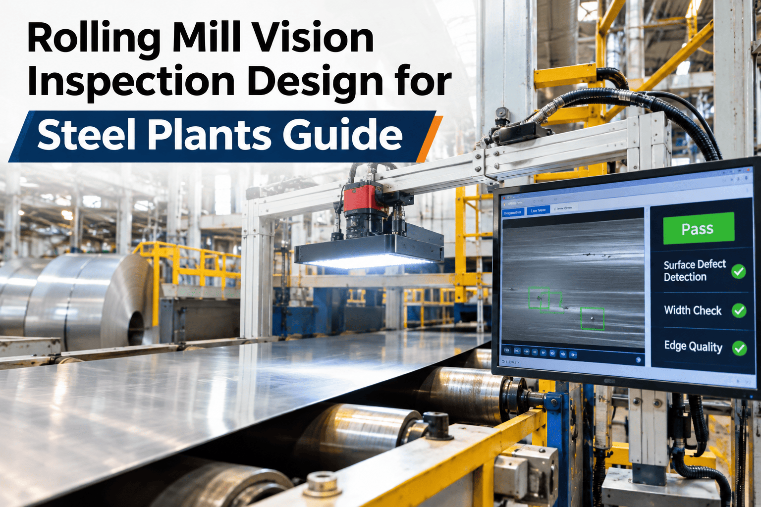
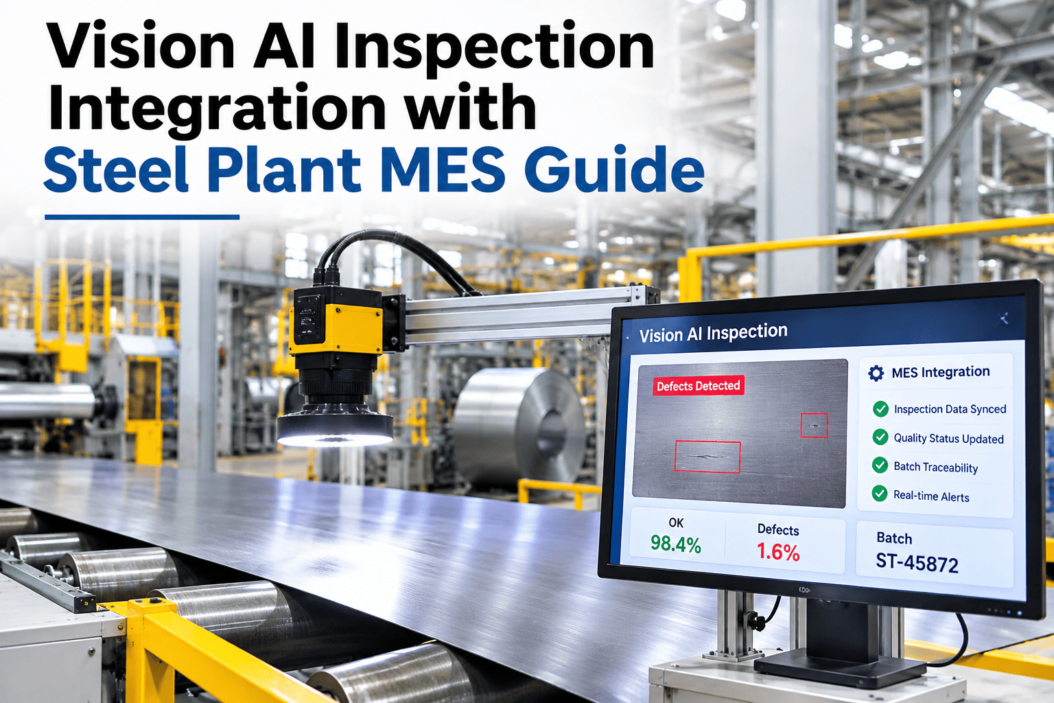
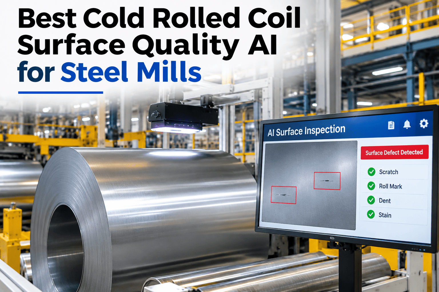
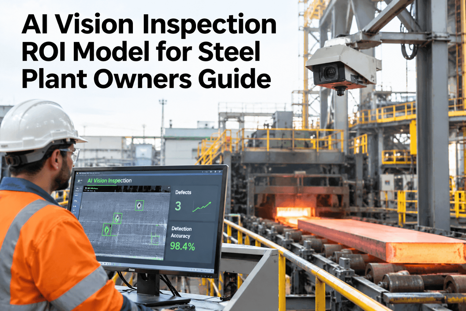
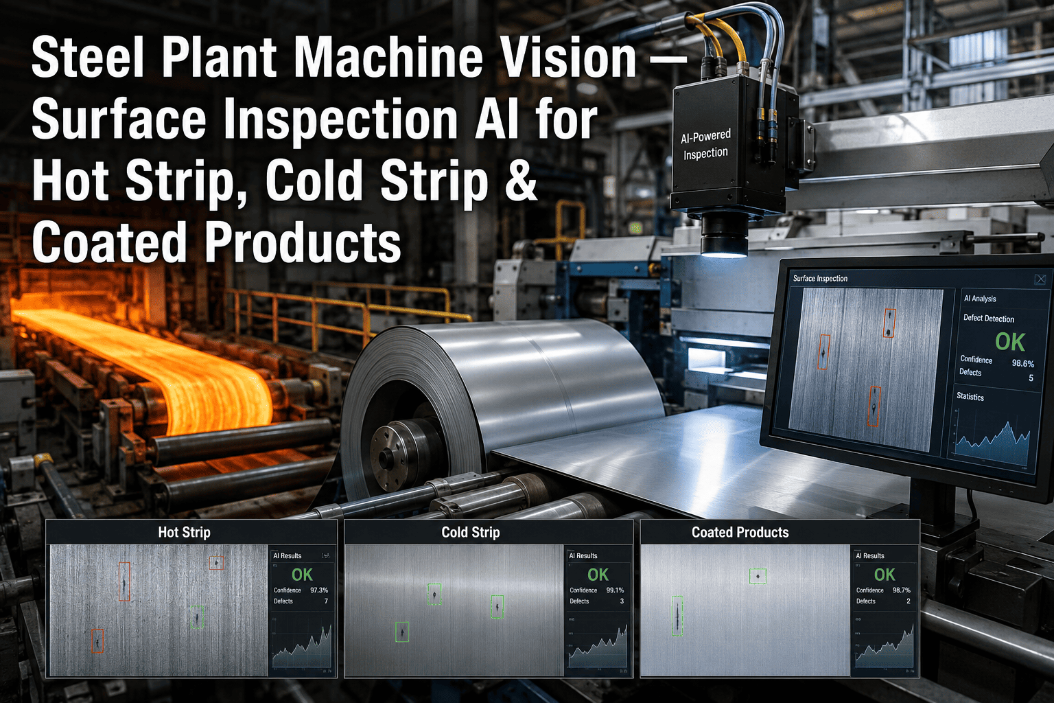
A vision inspection system that performs flawlessly in a vendor demo can fail completely once it is bolted onto a real rolling mill, because the demo rarely accounts for your actual lighting, your actual camera placement constraints, or your actual line speed. Getting inspection design right means tuning lighting for the surface you are actually imaging, placing cameras where they can actually see the defect zone, and matching shutter speed to the line speed so images come back sharp instead of blurred, and our team can walk through this design process against your own mill layout.
Hot and cold rolling mills, vision design
Design Vision Inspection That Actually Works at Your Mill's Line Speed
iFactory AI designs lighting, camera placement and shutter tuning around your actual mill conditions, so inspection performs the same on the floor as it does in review.
Why demos do not transfer
A Vendor Demo Rarely Matches Your Actual Mill Conditions
Demo footage is usually shot under ideal lighting, at a comfortable distance, on a line running at a convenient speed. None of those three conditions is guaranteed on your floor.
Different lighting
Hot surface glare or dim mill lighting changes everything
Different placement
Mill structure limits where a camera can actually go
Different speed
Your line speed determines whether a shutter setting freezes or blurs
System underperforms
Defects get missed that a lab test never would have caught
Three design elements
What Vision Inspection Design Actually Has to Get Right
Lighting design
Angle and intensity tuned to reveal surface defects without washing out the image.
Camera placement
Position and angle chosen to see the full defect zone within mill structural limits.
Shutter tuning
Exposure matched to line speed so moving surface images come back sharp.
Review Your Own Mill Layout
Share your line speed, surface type and current camera constraints and see what a tuned design would look like.
Design table
Matching Design Choices to Mill Conditions
| Condition | Design response | What it prevents |
|---|
| Hot surface glare | Angled lighting, polarizing filters | Washed-out or glare-obscured images |
| High line speed | Fast shutter, synchronized strobe lighting | Motion blur hiding fine defects |
| Limited mounting space | Compact camera housings, angled mounts | Blind spots in the defect zone |
| Dust or steam in the air | Air curtains, protective housings | Obscured lens and false readings |
Design process
Four Steps From Mill Layout to Working Inspection
1
Survey the line
Document line speed, surface type and available mounting points.
2
Design lighting and placement
Choose angle, intensity and camera position for the defect zone.
3
Tune shutter and capture rate
Match exposure settings to actual line speed, not a reference speed.
4
Validate on live product
Confirm image quality holds up across a full shift of real conditions.
Common pitfalls
Three Mistakes That Undermine Vision Inspection Design
1
Designing around a reference speed, not actual speed
Shutter settings tuned for a slower reference line blur badly at real speed.
2
Fixed lighting that ignores surface temperature changes
A hot surface at start of run looks very different by mid-run as it cools.
3
No validation across a full shift
A design validated for ten minutes misses drift that shows up over hours.
Expert review
The gap between a vision system that works in review and one that works on the floor is almost always lighting and shutter tuning, not the detection model itself. Get the image quality right first, because no model can classify a defect it cannot actually see clearly.
Watch for
A vendor proposal that specifies a detection model before specifying lighting and shutter settings for your actual line speed.
Do next
Test image quality at full line speed before evaluating any detection accuracy claims.
— iFactory steel specialists
Frequently asked questions
What Mills Ask About Vision Inspection Design
Does hot mill inspection need different lighting than cold mill?
Yes, a hot surface radiates its own light and glow which changes how lighting and camera exposure need to be set compared to a cold, reflective surface, so each needs its own design rather than one shared setup.
Discuss your hot or cold mill setup.
Can existing camera mounts be reused?
In many cases existing mounting points can work if they give a clear enough view of the defect zone, though some mills benefit from an added or adjusted mounting position once the survey is complete.
Ask about your current mounts.
What happens if line speed changes during production?
Shutter and capture settings can be tuned to handle a range of speeds, though the design should account for your actual operating range rather than a single fixed speed to avoid blur at the faster end.
Talk through your speed range.
How does dust or steam get handled in the design?
Protective housings and air curtains are common design responses for dusty or steamy environments, keeping the lens clear without blocking the camera's view of the surface.
Ask about your environment.
How long does a full design and validation process take?
A line survey followed by design and a validation period across a full shift typically gives a clear read on image quality before any detection model work begins.
Discuss your timeline.
From vendor demo to working inspection
Design Vision Inspection That Performs on Your Actual Floor
Book a session with iFactory AI to survey your mill layout and design lighting, placement and shutter settings for your real conditions.