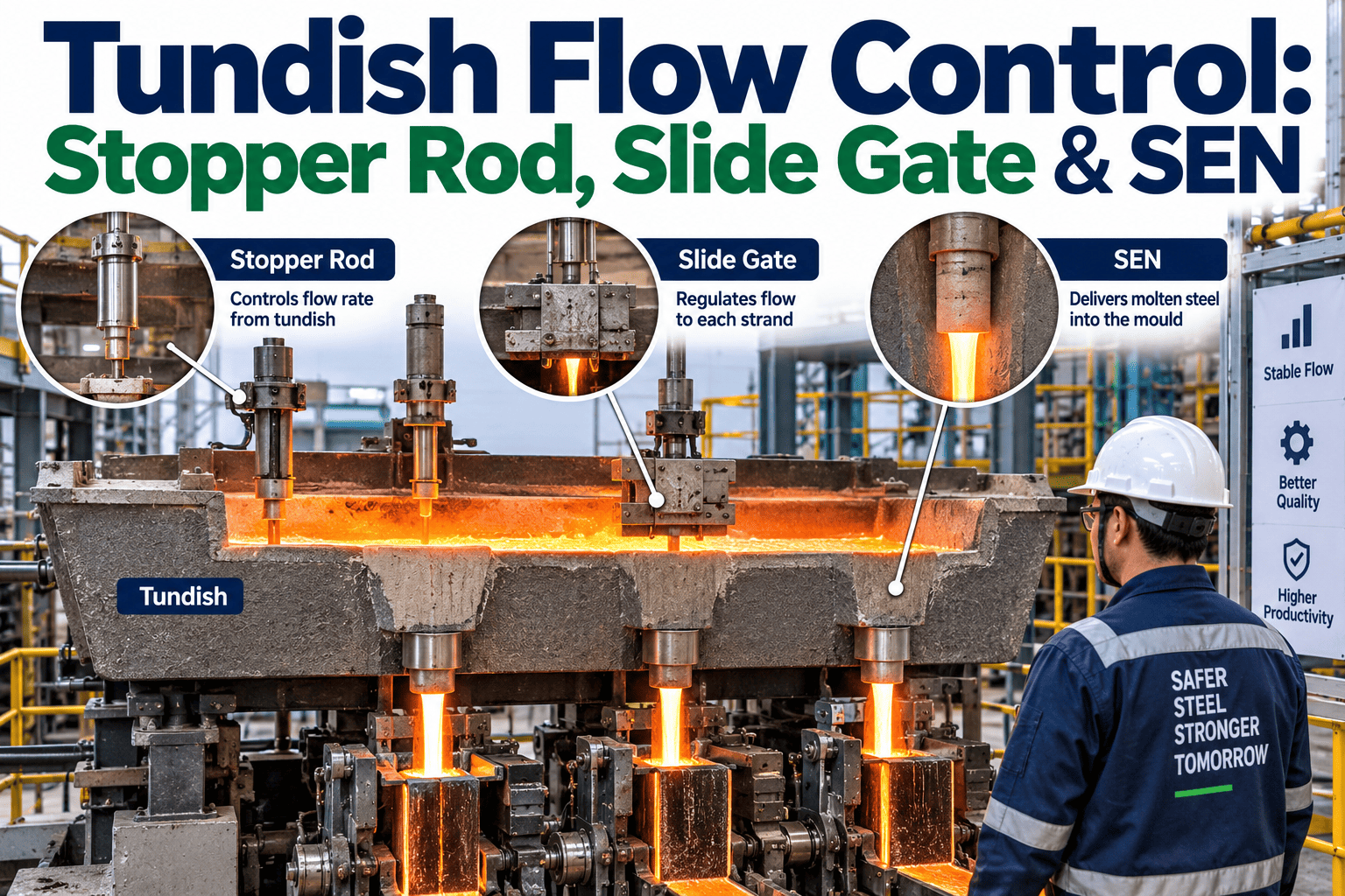
Every drop of steel that reaches the mold passes through three flow control points on the way — the tundish outlet, the stopper rod or slide gate that regulates it, and the submerged entry nozzle that delivers it into the mold cavity. None of these components fail suddenly. They drift, and that drift is exactly what determines whether the steel arriving in the mold is clean and steady or already carrying the inclusions and turbulence that show up as a surface defect two process steps later. Most casters can see the flow rate. Far fewer can see the drift itself while there's still time to act on it. To see how continuous flow-control monitoring catches that drift early, talk to our team at ifactory support.
The Stopper Rod Position Tells You What the Nozzle Won't Say Directly
Stopper rod, slide gate, and submerged entry nozzle condition don't fail as a single event — they drift together, and the position an operator has to hold the stopper at to maintain flow is one of the clearest early signals that something in the system is already changing.
The Path Steel Actually Takes, and Where It Can Go Wrong
Steel doesn't flow directly from tundish to mold in one uninterrupted stream. It passes through a metering point that regulates rate, a protective nozzle system that shields it from reoxidation, and finally the mold cavity itself. Each of these has a distinct job, and each degrades in its own characteristic way — which means a single "flow control problem" alert on a dashboard usually isn't specific enough to tell an operator which of the three is actually the issue, or which corrective action actually addresses the root cause rather than just the symptom currently visible on screen.
Stopper Rod vs Slide Gate: Two Ways to Meter the Same Flow
A stopper rod is a vertical refractory rod whose nose seats into the throat of the tundish outlet — raising it opens an annular gap that lets steel through, and the position of that rod is what an operator or control loop adjusts to hold flow rate steady. A slide gate does the same metering job differently, using a movable refractory plate that slides to misalign or align a bore with the nozzle beneath it. Neither design is universally better; each carries its own operating characteristics and its own failure signature.
| Characteristic | Stopper Rod | Slide Gate |
|---|---|---|
| Flow regulation | Smoother regulation via annular gap adjustment | Can introduce flow asymmetries inside the casting channel |
| Sensitivity | More sensitive to small displacement changes | Bore erosion progressively enlarges beyond design range |
| Nozzle exchange | Continuous nozzle design limits fast SEN swaps | Allows faster nozzle exchange during sequence changes |
| Emergency stoppage | Requires a separate means of emergency flow stop | Can seal flow directly through plate closure |
Talk Through Your Tundish, Stopper, and Nozzle Instrumentation
Bring your current flow control setup to the call. We'll walk through how continuous position and pressure tracking flags stopper drift and nozzle clogging before they interrupt a casting sequence.
Why the Stopper Position Is a Better Early Signal Than a Flow Alarm
A flow rate alarm only fires once the deviation is large enough to matter — by definition, it tells you about a problem that has already become significant. The position the stopper rod has to hold at a given, known casting speed tells a different and earlier story. If that position has to keep rising over the course of a sequence to maintain the same flow rate, the rod tip is eroding. If the position has to keep falling to maintain the same flow, alumina deposits are building up inside the nozzle bore and progressively restricting it. Both are drift signatures, and both are visible well before either one becomes a flow disruption an operator has to react to in the moment.
This is exactly why logging stopper position against cast speed set points, heat by heat, produces a trend line that's more useful than any single-point flow reading — the trend tells you which failure mode is developing and roughly how much runway is left before the flow control system can no longer compensate on its own.
Submerged Entry Nozzle Clogging: Why It's the System's Weakest Link
Nozzle clogging happens because alumina inclusions in the liquid steel deposit on the cooler inner bore surface of the SEN, gradually reducing the effective flow area available. As that deposit builds, the pressure drop across the nozzle increases, and the flow control system has to open further to compensate — right up until it can't compensate anymore, at which point the nozzle has to be swapped or the casting sequence stops entirely, both of which mean lost production time on top of the quality risk the buildup already created. The deposit isn't uniform either; it tends to concentrate at points of flow eddies and near the meniscus region on the outside of the nozzle, which is part of why clogging produces asymmetric mold level fluctuations rather than a clean, uniform flow reduction.
Argon gas injection through the stopper rod or a porous plug is the standard countermeasure, physically disrupting deposit formation before it accumulates. But argon line pressure and flow rate are themselves imperfect signals on their own — gas delivery pressure variation, leakage, and the actual volume reaching the nozzle all introduce noise that makes a single argon reading hard to interpret in isolation. Correlating argon behavior against stopper position and casting speed, rather than reading any one signal alone, is what turns a noisy indicator into a reliable one, and it's also what makes it possible to tell a genuine clogging trend apart from ordinary gas supply variation that has nothing to do with nozzle condition.
Where Reoxidation Sneaks Back Into a Protected System
The entire point of a submerged entry nozzle is to shield steel from atmospheric reoxidation as it travels from tundish to mold — but the flow control system itself can undermine that protection. When a slide gate or stopper rod restricts flow enough to drop internal nozzle pressure below atmospheric, air can be drawn in through any crack or gap in the refractory, introducing exactly the oxide inclusions the nozzle was designed to prevent. This effect intensifies as clogging progresses, since a more restricted bore requires a tighter opening to maintain flow, which lowers internal pressure further and increases aspiration risk — meaning a nozzle that's already clogging can accelerate its own contamination.
The Tundish Itself: More Than a Holding Vessel
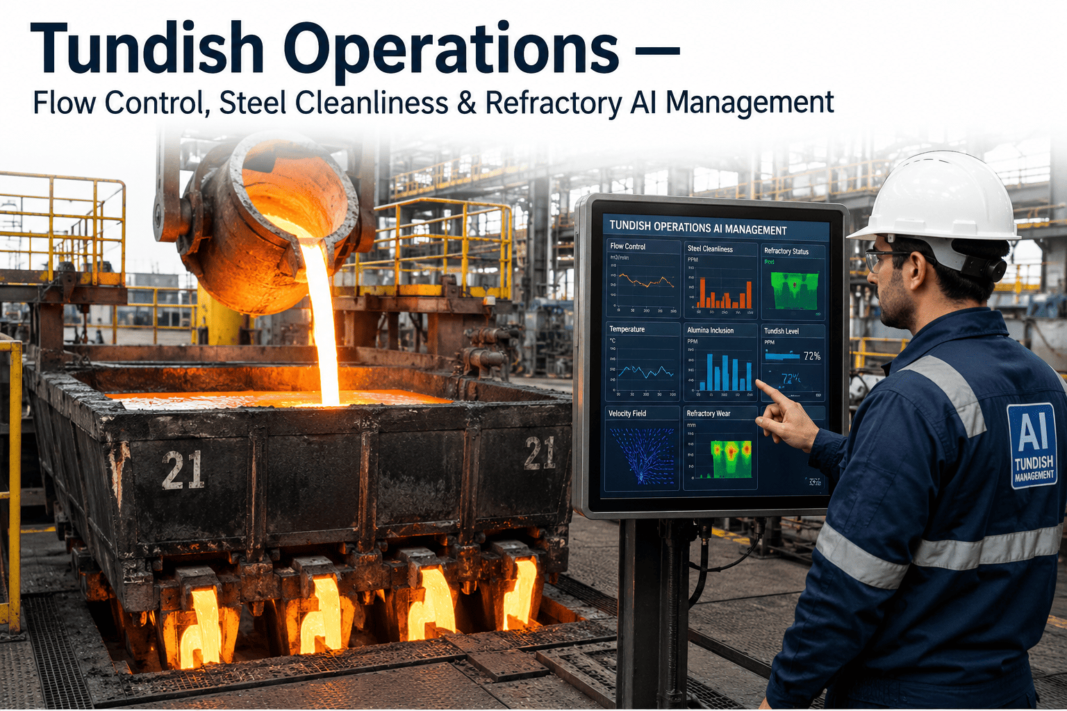
It's easy to think of the tundish as simply a buffer that sits between the ladle and the mold, smoothing out the transition from one ladle to the next. In practice it performs several distinct jobs at once, and flow control quality depends on all of them working together. It acts as a thermal buffer, evening out temperature swings between ladles so the steel reaching the mold stays within a consistent casting temperature window. It's also an inclusion flotation chamber, giving non-metallic inclusions time to rise out of the steel before it ever reaches the nozzle — a function that depends heavily on residence time and internal flow pattern, both of which are shaped by weirs, dams, and other flow-modifying devices inside the vessel. On multi-strand casters, it's simultaneously a distribution manifold, splitting flow evenly across every strand fed from the same tundish.
Because the tundish performs all of these functions at once, a flow control problem rarely stays isolated to a single strand or a single symptom. A refractory issue that disrupts internal flow pattern can quietly undermine inclusion flotation even while the metering system downstream looks like it's operating normally, which is part of why flow control monitoring needs to look upstream of the stopper rod and nozzle, not just at them.
How Flow Control Drift Becomes a Rolled-Product Defect
The gap between a flow control problem and its visible consequence is one of the reasons these issues are so easy to under-prioritize in the moment. A stopper rod that's had to drift its position by a few millimeters over a sequence doesn't look alarming on its own. But that drift changes flow rate consistency into the mold, which disturbs meniscus stability, which affects how evenly the solidifying shell forms, which shows up much later as a surface crack or an inclusion cluster on the rolled coil — discovered by a completely different team, often days after the heat that actually caused it was cast.
| Stage | What Happens | Where It Surfaces |
|---|---|---|
| Nozzle bore narrows | Alumina deposit reduces effective flow area | Invisible without position or pressure trending |
| Flow rate becomes asymmetric | Uneven deposit pattern skews delivery into the mold | Mold level sensor shows erratic fluctuation |
| Meniscus stability disrupted | Uneven shell formation begins at the surface | Not visible until the strand solidifies further |
| Surface defect forms | Crack or inclusion cluster embedded in the strand | Discovered on rolled product, often days later |
Four Signals Worth Watching Together, Not Separately
Frequently Asked Questions
Monitor Stopper Position, Argon Behavior, and Nozzle Condition Together
A turnkey AI deployment correlates stopper position, argon line behavior, and mold level fluctuation in one continuous view, flagging tip erosion and nozzle clogging early enough to act before a casting sequence is disrupted.