A roving frame that drifts even slightly out of calibration does not announce itself. The bobbin still builds, the flyer still turns, and the shift log still shows normal output — right up until the ring frame downstream starts throwing end breaks nobody can explain. Roving twist multiplier, tension setting, and bobbin build geometry are the three quiet variables that decide whether the next process runs clean or fights itself all shift. Get a walkthrough of live roving frame parameter tracking with Book a Demo.
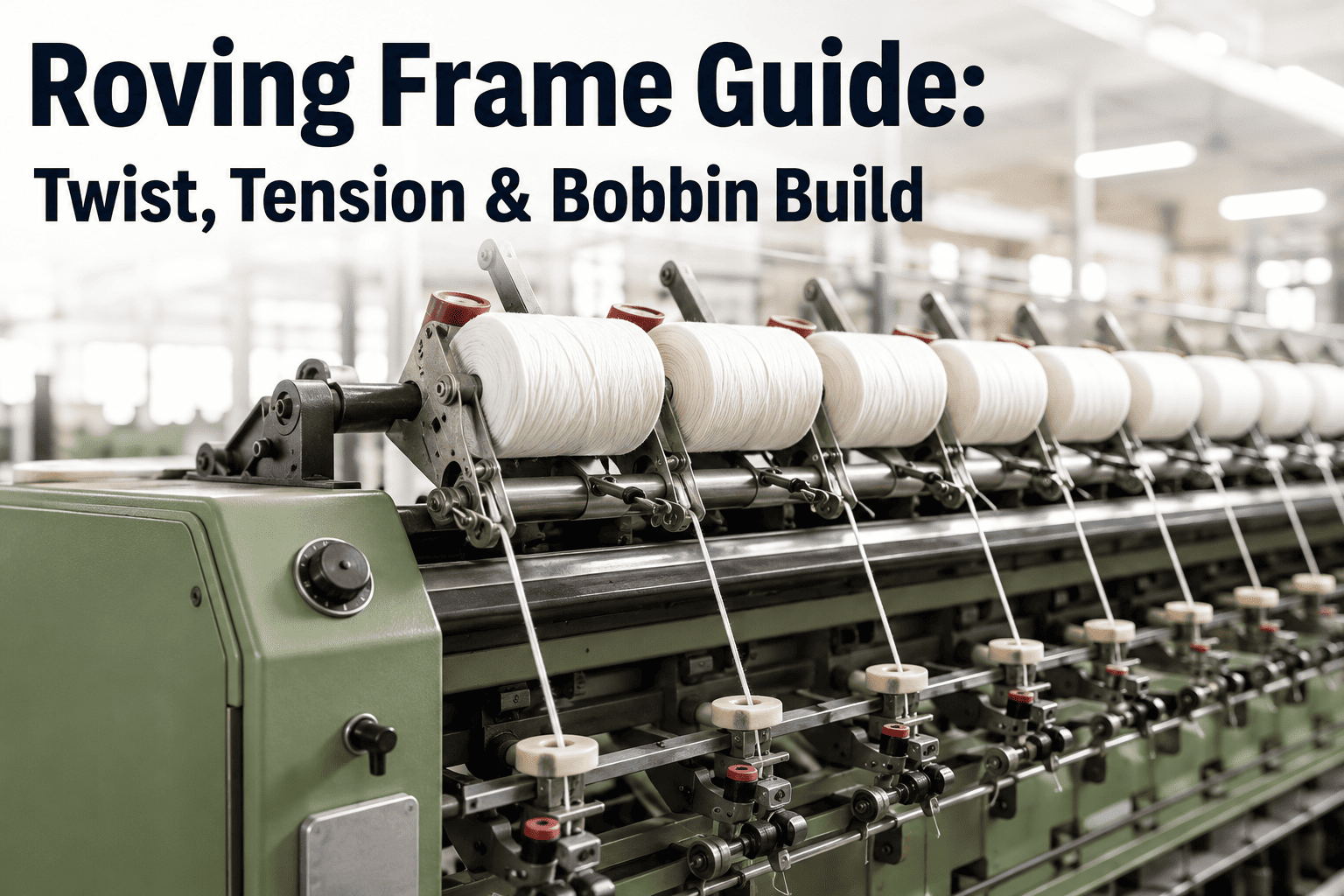
Roving Frame Guide: Twist, Tension & Bobbin Build
A practical breakdown of the flyer speed, twist multiplier, and winding pattern settings that determine roving quality — and how continuous monitoring catches drift before it reaches the ring frame.
Every Roving Quality Issue Traces Back to One of These Dials
Roving frames look mechanically simple compared to a ring frame, which is exactly why drift in these three settings goes unnoticed the longest. Each dial below governs a distinct quality outcome, and each has a narrow band where the roving actually performs.
Twist Multiplier
Governs roving strength versus drafting ease at the ring frame. Set too high, the roving resists draft and creates thick places. Set too low, it lacks the cohesion to survive transport and creping.
Flyer Speed
Determines both productivity and the centrifugal tension the roving experiences as it winds. Pushed beyond the frame's stable range, flyer speed introduces ballooning and uneven lay.
Winding Tension
Controls how tightly roving packs onto the bobbin. Excess tension causes stretch and count variation; insufficient tension produces soft, sloughing-prone packages that collapse in transit.
Draft roller delivers sliver at set draft ratio
Flyer inserts twist as roving passes through
Presser arm guides roving onto bobbin surface
Bobbin rail shifts to build the winding pattern
Cop builds base-to-nose taper for stable transport
Catch Roving Drift Before the Ring Frame Does
See how continuous parameter tracking flags twist, tension, and build deviations while the frame is still running.
Typical Twist Multiplier Ranges by Roving Hank
These ranges are starting points, not fixed rules — fiber type, humidity, and downstream draft capability all shift the workable band. Use them as a baseline before fine-tuning to your own machine and material.
| Roving Hank | Typical TM Range | Flyer Speed (rpm) | Primary Risk if TM Too Low | Primary Risk if TM Too High |
|---|---|---|---|---|
| 0.6s–0.8s | 1.1–1.3 | 900–1000 | Roving sag, breaks in creel | Draft resistance at ring frame |
| 0.9s–1.2s | 1.2–1.4 | 1000–1100 | Sloughing off bobbin | Uneven drafting force |
| 1.3s–1.6s | 1.3–1.5 | 1050–1150 | Snarling during transport | Thick and thin places |
| 1.7s–2.2s | 1.4–1.6 | 1100–1200 | Poor cohesion, false twist loss | Reduced spinning limit downstream |
Why Bobbin Build Shape Matters as Much as Twist
A roving bobbin that builds correctly protects the roving from the moment it leaves the flyer until it is mounted on the ring frame creel. Build faults rarely cause immediate breaks — they cause the intermittent, hard-to-trace defects that show up two processes later.
Base Diameter Consistency
An uneven base layer telegraphs upward through every subsequent layer, producing a bobbin that runs off-center and strains the roving under uneven tension during unwinding.
Traverse-to-Rotation Ratio
The rail traverse speed relative to spindle rotation sets the winding angle. Mismatched ratios create loose coils that shift and tangle before the bobbin ever reaches the creel.
Nose and Base Taper
Proper taper at both ends lets the roving unwind under constant, low tension at the ring frame creel. A flat-ended build causes tension spikes as the unwinding point jumps.
Package Density
Overly dense packages resist unwinding and add drag at the creel; underdense packages collapse under their own weight during transport between departments.
What Roving Drift Looks Like Before It Reaches the Ring Frame
Roving diameter variation visible along the length of a single bobbin, often traced back to draft roller wear rather than the flyer itself.
Snarling or kinking during doffing, typically indicating twist multiplier set too low for the current hank and fiber combination.
Bobbins that lean or wobble on the creel peg, pointing to inconsistent base diameter from a build geometry fault.
A rising trend in ring frame end breaks with no change on the ring frame itself, which almost always traces back to the roving supplying it.
Frequently Asked Questions
Q: How often should twist multiplier be verified on a running roving frame?
Most mills check twist multiplier once per shift using a manual twist tester, which means drift can run for hours before anyone notices. The gap between manual checks is exactly where quality loss accumulates fastest, since a flyer speed sensor drifting a few percent will not trigger any alarm on its own. Continuous monitoring closes that gap by comparing actual flyer rpm and delivery rate against the target twist multiplier in real time, flagging deviation the moment it starts rather than at the next scheduled check. Ask about live twist tracking with Book a Demo.
Q: What is the relationship between winding tension and downstream spinning limit?
Winding tension that runs too high stretches the roving during package build, which permanently reduces its cross-sectional consistency before it ever reaches the ring frame. That stretch shows up downstream as an artificially lowered spinning limit, since the ring frame drafting system now has less consistent material to work with regardless of how well the ring frame itself is set. Correcting winding tension at the roving frame is almost always cheaper than trying to compensate for it further down the process chain.
Q: Can the same twist multiplier setting be used across different fiber types?
No. Twist multiplier ranges that work well for cotton typically need adjustment for polyester-cotton blends and viscose, since fiber friction and cohesion characteristics differ significantly between materials. A blend with lower inter-fiber friction generally needs a slightly higher twist multiplier to achieve the same roving cohesion that a pure cotton roving reaches at a lower setting. Running one universal setting across all materials is a common source of inconsistent bobbin build quality across product changeovers.
Q: How is bobbin build geometry actually measured in production?
Traditional measurement relies on periodic manual inspection of doffed bobbins, checking base diameter, taper angle, and package density by eye and caliper against a reference sample. This catches gross faults but misses gradual drift in the traverse mechanism that produces a slowly worsening build over many doffs. Camera-based monitoring at the doffing point can capture build geometry on every single bobbin automatically, building a trend line that shows drift long before it becomes a visible fault. Reach out through Support Contact to review build monitoring for your frame configuration.
Q: What is the fastest way to diagnose a sudden rise in ring frame end breaks?
Before adjusting anything on the ring frame itself, pull a sample of the roving currently feeding it and check twist multiplier, roving diameter uniformity, and bobbin build condition against baseline. A disproportionate share of sudden end break increases trace back to a roving frame parameter that drifted during the current run rather than anything on the ring frame. Checking upstream first typically resolves the issue faster than adjusting ring frame tension settings that were never the actual cause.
Turn Roving Frame Parameters Into a Trend Line, Not a Guess
See continuous twist, tension, and build monitoring running against your own roving frame data.