Casting Defect Analysis: Porosity, Shrinkage and AI X-Ray
By Josh Brook on October 21, 2026
A casting that passes visual checks can still carry a void in a sealing face or a crack beside a bolt boss. Radiography finds it, but radiographs are often graded by eye, image by image, and the result rarely makes its way back to the die or the pour. Casting defect analysis closes that loop: name the defect, grade it against a reference, map where it sits and link it to the process data that made it. To see AI grading on real foundry images, book a short X-ray AI demo.
X-RAY AI · CASTING QUALITY
Grade Every Radiograph and Trace Each Defect to the Shot That Made It
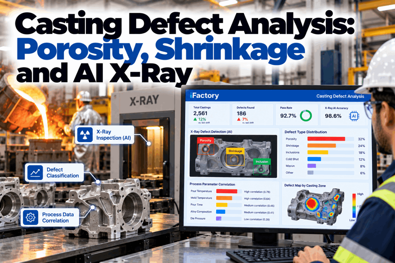
iFactory X-Ray AI + Process Data classifies porosity, shrinkage, inclusions and cold shuts on each image, builds defect maps by casting zone and lines them up with pour, die and alloy data. Your radiographers confirm the calls that matter.
Sent to radiographer for sign-off · cell lead alerted
POROSITY CASTINGS
Gas or Shrinkage? Read the Shape Before You Chase the Cause
Both show up as dark spots on a radiograph, but they come from different places and need different fixes. Gas porosity forms when gas comes out of the metal or the mould as it freezes. In aluminium, hydrogen dissolves roughly twenty times more readily in the liquid than in the solid, so it is pushed out as the metal sets. Shrinkage forms when a section loses volume while freezing and no liquid metal is left to feed it. The clues below are strong hints, not proof, and the two often occur together. Talk through your own images with our casting quality team.
Gas porosityClueShrinkage porosity
Round or oval, smooth edges
Shape
Jagged, branched or sponge-like
Scattered pores, clusters or fine pinholes
Pattern
One cavity or a connected network
Near the top surface, cores, blind pockets or where flows meet
Where
Heavy sections, bosses and junctions that freeze last
Melt hydrogen, damp tools or cores, venting, turbulent fill
Check first
Feeding, risers or intensification, section changes, die heat
RADIOGRAPHY DEFECTS BEYOND POROSITY
Inclusions, Cold Shuts, Misruns and Hot Tears
Porosity gets the attention, but four other defect types cause their share of scrap and field returns. Each leaves a different mark on the film or the part and points to a different step in the process. A cold shut and a misrun both mean the metal froze before it should have. A hot tear means the casting was pulled apart while still weak. Review your defect catalogue in a defect mapping session.
Inclusions
On the filmIrregular spots, lighter or darker than the metal around them
Usual causeOxide film, slag, dross or sand washed from the mould
On the filmA fine line or seam where two metal fronts met but did not fuse
Usual causeLow metal or die temperature, slow fill, poor venting
Check firstPour or shot temperature, gate speed, overflows and vents
Misruns
On the partA section not filled at all, often thin walls far from the gate
Usual causeMetal freezes before the cavity is full
Check firstPour temperature, fluidity, wall thickness, fill time
Hot tears
On the filmRagged, branching dark lines, often at section changes
Usual causeContraction held back by a stiff core or mould while hot
Check firstFillet radii, core collapsibility, mould or die temperature
REFERENCE RADIOGRAPHS
ASTM E155, E505 and E446: Which Set Fits Your Castings
Most casting buyers don't write "no porosity" on a drawing. They name a reference radiograph standard and a severity level per zone. These ASTM sets show graded examples of each defect type, and the general rule is that a defect equal to or less severe than the named level is acceptable. Digital reference images now exist for some sets, such as ASTM E2422 for aluminium castings, for use with digital radiography. Check which set your customers specify with our quality engineers.
Standard
Castings covered
Thickness range
Defect categories shown
Grading
ASTM E505
Aluminium and magnesium die castings
Up to 1 in (25 mm)
A porosity, B cold fill, C shrinkage, D foreign material
4 levels for A to C
ASTM E155
Aluminium and magnesium castings
Images at 1/4 in and 3/4 in, applied up to 2 in
Gas holes, gas porosity, shrinkage cavity and sponge, foreign material
Up to 8 grades
ASTM E446
Steel castings
Up to 2 in (51 mm)
A gas porosity, B sand and slag inclusions, C shrinkage types CA to CD
5 levels for A to C
ASTM E446 ungraded
Steel castings
Up to 2 in (51 mm)
D cracks, E hot tears, F chaplets and chills, G mottling
Examples only
ASTM E2422
Aluminium castings, digital images
Images at 1/4 in and 3/4 in, applied up to 2 in
Digital counterpart for E155 style aluminium defects
8 grades
SEVERITY GRADING
One Defect, Two Zones, Two Different Answers
A severity level only means something next to the limit for that zone. A sealing face or a highly stressed bolt boss usually gets a tight limit, while a cover flange may accept far more. That is why the same image can pass in one place and fail in another, and why grading without a zone map produces arguments with customers. The example below is an illustration using the four-level E505 porosity scale. Set zone limits with our grading specialists.
Sealing faceLimit: level 1
1234
Level 3 found · reject
Cover flangeLimit: level 3
1234
Level 3 found · accept
Within limitBeyond limitLevel found
From a Dark Spot on an Image to a Fix at the Machine
iFactory reads each radiograph, grades the defect against the limit for its zone and checks the shot or pour data behind it. When a pattern appears, the cell lead hears about it during the shift, not at next week's quality meeting.
Quality leadWhy are we seeing more holds on the housing since lunch?
iFactoryEleven of the last 60 shots show sponge shrinkage in zone 6. All eleven ran with die zone 6 below its usual temperature band.
Quality leadAnything on the gas side?
iFactoryNo. Gas porosity levels are flat and the last melt hydrogen check was in range. This looks like a feeding problem, not a melt problem.
DIE CASTING QUALITY AND POUR TEMPERATURE
The Process Variables Behind Each Defect
High pressure die casting and sand casting fail in different ways because they fill and freeze differently. In die casting, the shot profile, die temperature and intensification pressure decide most of the porosity story. In sand casting, pour temperature, feeding and mould moisture carry more weight. In both, melt hydrogen in aluminium is a shared suspect for gas porosity. Linking each defect to these variables is what turns an inspection result into a fix. Map your own process signals with our process engineers.
High pressure die casting
Die temperatureCold zones freeze early, hot zones freeze lateCold shuts, shrinkage
Intensification pressureToo low or too late and late-freezing areas are not packedShrinkage porosity
Shot speed and fillTurbulent fill traps air and die spray vapourGas porosity
Vacuum and ventingAir left in the cavity has nowhere to goGas porosity, blisters
Melt hydrogenMore dissolved gas to release as the metal freezesGas porosity
Sand casting
Pour temperatureToo low limits fluidity, too high adds gas and shrinkageMisruns, cold shuts, shrinkage
Risers and feedingHeavy sections outside a riser's reach starveShrinkage cavity
Sand moisture and coresSteam and binder gas enter the metalGas holes, blowholes
Pouring practiceFast or turbulent pours wash sand and fold in oxideInclusions
Core and mould stiffnessRigid cores resist contraction while hotHot tears
DEFECT MAPS BY CASTING ZONE
A Heat Map That Shows Where Defects Gather
One rejected casting is an event. Fifty images mapped onto the same casting zones show a pattern. A heat map by zone and day tells you whether a defect is tied to one location, one machine state or one period of production, and that decides who gets the problem. The example below is an illustration of a week on one part number, not real plant data. See your own part maps in a zone map walkthrough.
ZoneMonTueWedThuFri
Z2 thin wall02101
Z4 sealing face32323
Z5 rib junction10561
Z6 bolt boss129112
Z8 far end01010
PatternZ5 and Z6 spike Wed to Thu
Process linkDie cooling circuit 6 flow low
Steady signalZ4 low level every day, watch
X-RAY INSPECTION AI
From Digital Radiograph to a Graded, Linked Defect
Film radiography still exists, but digital radiography and CT are what make automated grading practical. Digital images arrive in seconds and can be compared with the same reference every time. CT goes further, placing each void in three dimensions so you know its depth and whether machining will open it. The AI does the first pass and the sorting. A qualified radiographer still signs off rejects and any call your customer requires a person to make. Ask our support team how this fits your inspection procedure.
1
CaptureDigital radiograph or CT scan, tagged with part, cavity and shot number
2
Align to zonesImage matched to the part's zone layout and its limits
3
ClassifyGas, shrinkage, inclusion, cold shut or tear, with location and size
4
GradeSeverity compared with the named reference level for that zone
5
LinkPour, die, shot and melt data for that casting pulled alongside
6
ConfirmRadiographer signs off rejects, an audit sample of passes is reviewed
CASTING DEFECT ANALYSIS BEST PRACTICES
Habits That Make the Analysis Worth Doing
The software matters less than the discipline around it. These practices come up again and again in foundries that get real value from defect data. Talk through which ones fit your plant on a foundry review call.
Instead ofGrading the whole casting with one limitDo thisSet a reference level per zone, agreed with the customer
Instead ofRecording "porosity, reject"Do thisRecord type, zone, size and level every time
Instead ofLinking defects to a dateDo thisLink to shot number, cavity, melt and die state
Instead ofMeasuring hydrogen when there is a problemDo thisCheck melt gas on a schedule and log the result
Instead ofReviewing scrap once a monthDo thisWatch zone trends daily and act on a shift
Instead ofTrusting AI calls blindlyDo thisKeep human sign-off on rejects and audit a sample of passes
CASTING DEFECT ANALYSIS COST AND ROI
A Worksheet You Can Fill With Your Own Numbers
Two parts of the value are easy to size: radiographer time spent on clear passes, and what each point of porosity scrap costs you. Every input below is an assumption to show the arithmetic, so replace each with your own figures. No reduction is assumed. Our team can help you build the full case.
Review time
Radiographs per day, assumed1,200
Review time per image, assumed20 s
Manual review of all images1,200 × 20 s = 400 min
Images flagged by AI, assumed 15%180 × 20 s = 60 min
Audit sample of passes, assumed 5%60 × 20 s = 20 min
Radiographer time freed per day400 − 80 = 320 min
Value of one scrap point
Castings poured per day, assumed2,000
Cost per scrapped casting, assumed$45
Castings in 1% of output2,000 × 1% = 20
Cost of 1% porosity scrap per day20 × $45 = $900
Production days per year, assumed250
Cost of each 1% per year$900 × 250 = $225,000
TURNKEY AI DEPLOYMENT
X-Ray AI, Process Links and AI Server in One Package
iFactory delivers X-Ray AI + Process Data as a turnkey bundle. A pre-configured NVIDIA AI server ships racked and ready with the defect classification models and data connectors pre-loaded, so radiographs are processed on site and never leave the plant. You rack it, plug in power and Ethernet, and the AI is live. To scope it for your foundry, request a turnkey quote.
What's Included
Pre-configured NVIDIA AI edge server, racked and ready
Defect models for porosity, shrinkage, inclusions, cold shuts and tears
Connector to your digital radiography or CT system
Zone layouts and limits loaded per part number
Links to die casting cells, pour records and melt checks
Defect maps, trend views and alerts for cell leads
24×7 remote monitoring of models and hardware
Live in 6–12 weeks
Wk 1–4
Connect and Load
Server installed, X-ray system and process data linked, zones and limits loaded for the first parts.
Wk 5–8
Shadow Grading
AI grades in the background while radiographers compare its calls with their own.
Wk 9–12
Go-Live and Training
AI pre-sort switched on, cell leads trained on zone maps and process alerts.
HOW iFACTORY FITS
Casting Defect Analysis Software Built for the Foundry Floor
iFactory connects the X-ray room to the cells and the melt shop, so quality and process teams work from the same evidence. Our support team can walk you through a pilot plan.
1
Automated radiograph classification. Each image is sorted by defect type, size and severity level.
2
Defect maps by casting zone. Results are plotted on the part's zones and graded against each zone's limit.
3
Pour, die and alloy correlation. Every defect sits next to the shot, die temperature and melt data behind it.
4
People keep the final say. Rejects go to a qualified radiographer for sign-off, with images and data attached.
1000+
Industrial clients running iFactory
99.9%
Platform uptime for round-the-clock casting
6-12 wks
From racked server to live X-ray grading
FREQUENTLY ASKED QUESTIONS
What Plant Managers Ask About Casting Defect Analysis
How do you tell gas porosity from shrinkage on an X-ray?
Gas pores are usually round with smooth edges and appear scattered or in clusters near top surfaces, cores or vents. Shrinkage is jagged, branched or sponge-like and sits in heavy sections and junctions that freeze last. These are strong hints rather than proof, and both can occur together, so the process data behind the casting helps confirm the cause.
Which reference radiographs apply to our castings?
It depends on alloy and process. ASTM E505 covers aluminium and magnesium die castings up to 1 in thick. ASTM E155 covers aluminium and magnesium castings with images applied up to 2 in. ASTM E446 covers steel castings up to 2 in. Your customer's drawing or purchase order normally names the set and the severity level for each zone.
Can AI replace a qualified radiographer?
It should not be set up that way. AI is good at grading every image the same way and sorting clear passes from likely rejects, which saves time. Customer specifications and your own procedures usually require a qualified person to make or confirm the reject decision, so iFactory routes those calls to a radiographer with the image and data attached.
What process data should be linked to each casting?
For die casting, start with shot number, cavity, die zone temperatures, shot speed profile and intensification pressure. For sand casting, pour temperature, pour time, sand moisture and core batch. For aluminium in both, add melt hydrogen or density test results. Even a few of these signals turn a reject list into a cause list.
Does it work with film radiography?
Automated grading needs digital images, so it works best with digital radiography or CT. Some plants digitise film for a transition period, but image quality varies. Most foundries that want AI grading on a running line move the relevant stations to digital radiography first.
What is the best way to start?
Pick one part number with a known porosity problem and a digital X-ray station. Load its zones and limits, link its shot or pour data and run the AI in shadow mode while radiographers compare results. Once the calls agree, switch on the pre-sort and the zone maps. Our support team can plan that first part with you.
Every Radiograph Graded, Every Defect Traced
Classify every image, map defects to casting zones and see the pour, die and alloy data behind each one. The full system is delivered turnkey and goes live in 6 to 12 weeks.