CNC Machining Quality Control: In-Process Gauging and AI
By James C on October 21, 2026
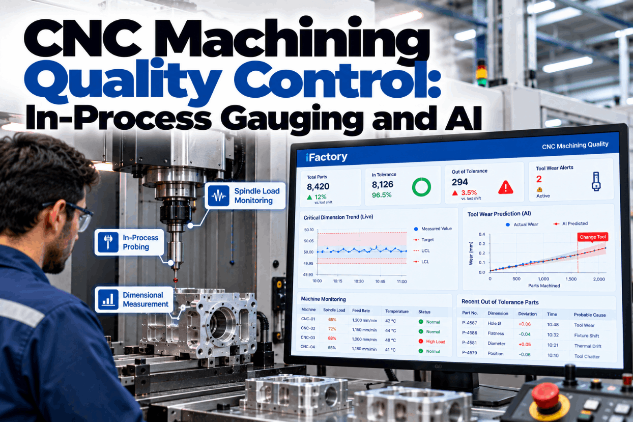
A CNC program that made a perfect first article can still make scrap by mid-shift. The cutting edge wears, the spindle warms up and the bore that measured on size at 7 a.m. is creeping toward its lower limit by lunch. Final inspection finds it after a whole batch is cut. CNC machining quality control works best when the machine measures itself during the cycle and the trend is read before the part goes out of tolerance. See drift prediction on real probe data in a short machining quality demo.
PROCESS QUALITY · CNC MACHINING
Predict Dimensional Drift Before the Next Part Goes Out of Tolerance
iFactory Machining Quality AI combines in-process probe readings with spindle load to predict drift on each machine. It runs SPC on critical dimensions and recommends an offset or a tool change, with a person approving every change.
Recommended · awaiting cell leadT12 radius wear offset −0.005 mm to centre bore at 25.000
Approve · Edit · Reject · every choice logged per machine
DIMENSIONAL DRIFT
Four Reasons a Proven Program Starts Making Bad Parts
Dimensional drift rarely comes from the program itself. It comes from things that change while the program runs. Each source drifts on its own timescale, which is why one end-of-batch check can't catch them all. Knowing the timescale tells you how often to probe and what the AI should watch. Talk through your own drift sources with our machining team.
Tool wearCutting edges wear with every part, so sizes move steadily in one direction.Timescale: parts to hours
Thermal growthSpindle, ball screws and frame expand as the machine warms and shrink when it stops.Timescale: minutes to a shift
Setup and workholdingChips under a part, clamp force or a new fixture shift where the part sits.Timescale: each load or setup
Material and stockHardness or stock size changes between lots shift cutting forces and deflection.Timescale: each lot
CNC MACHINING QUALITY CONTROL BEST PRACTICES
In Process Probing at Every Layer of Process Control
Renishaw's Productive Process Pyramid is a useful way to sort machining controls. The base keeps the machine and process stable before cutting. Above it, probing sets up the part and tools, controls the process during cutting, and verifies the result before the part leaves the machine. In-process control is where drift is caught, because the probe feeds back tool wear and thermal effects while machining continues. Map your controls to each layer in a process review.
Post-process monitoringOn-machine verification of critical features, reports, history for SPC
In-process controlIn-cycle gauging adjusts offsets for wear and heat, broken tool checks
Process settingFind the part and datums, measure tool length and diameter
Process foundationMachine condition, warm-up, fixtures, stable conditions before the first cut
ON-MACHINE VERIFICATION
What to Probe, When, and What the Result Changes
A touch-trigger probe in the spindle signals the control the moment the stylus touches a surface, and the control records the axis position. A tool setter on the machine bed measures tool length and diameter and spots broken tools. Each probing cycle adds time, so probe the features and moments that matter most, not everything on every part. Plan your probing routine with our support team.
Check
Device
When
What the result changes
Part location and datums
Spindle probe
Each load
Work offset
Tool length and diameter
Tool setter
New tool, after a change
Tool geometry offset
Broken tool
Tool setter
After heavy or small tools
Stop cycle, call operator
Critical feature size
Spindle probe
Every nth part, before finish pass
Wear offset, within limits
Reference artefact
Spindle probe
After warm-up and long stops
Thermal check, hold or proceed
Finished feature
Spindle probe
Before unload
Accept, flag or quarantine part
TOOL WEAR COMPENSATION
Turning a Probe Reading Into the Right Offset
When a feature drifts because the tool is wearing, the fix is usually a wear offset, not a program edit. The arithmetic is simple but easy to get wrong under pressure, especially the difference between diameter and radius. The example is a bore milled by circular interpolation with cutter compensation, so the wear offset is a radius value and half the diameter error. Check your own offset rules with our applications engineers.
Nominal bore25.000 mm
Probe mean, last 5 checks24.990 mm
Diameter error24.990 − 25.000 = −0.010 mm
Radius wear offset change−0.010 ÷ 2 = −0.005 mm, a smaller radius value moves the path out and opens the bore
Dead bandNo change for errors smaller than measurement noise
Step limitEach change capped, larger errors go to a person
Total wear capPast the cap, change the tool instead
VerifyNext part probed to confirm the change worked
Offsets Proposed by AI, Approved by Your People
iFactory reads probe and spindle data from every machine, predicts how many parts are left before a feature leaves tolerance and proposes an offset or tool change with the evidence attached. The cell lead decides.
Cell leadWhy offset T12 again? We did it this morning.
iFactoryBore mean is 24.990 and falling about 0.001 every 5 parts. Total wear comp on T12 would reach 0.015 of your 0.020 cap.
Cell leadAnd after that?
iFactorySpindle load on T12 is also rising. I recommend this offset now and a tool change at the next pallet swap. Both are waiting for your approval.
SPINDLE LOAD QUALITY
Spindle Load as an Early Wear Signal
As an edge dulls, it takes more power to cut, so spindle load for the same tool and the same feature tends to rise across its life. Load is read from the control on every part, while probing may only run on every fifth, so the two together give a fuller picture. Load can also rise for other reasons, such as harder stock or a spindle bearing problem, which is why the AI reads it with probe data rather than alone. The chart is illustrative. Send sample data to our data team.
T12 · Ø12 end mill · finish boreAverage spindle load per 10 parts
0
10
20
30
40
50
60
70
Change-tool band
Parts cut on this edge
Adjust the offset whenSize drifts slowly, load rises gently and total wear comp is well under the cap.
Change the tool whenLoad climbs fast, finish worsens, wear comp nears the cap or the size trend speeds up.
THERMAL GROWTH
Probe Around the Machine's Warm-Up, Not Just the Clock
Heat from the spindle bearings, motor and slideways moves into the casting, so the spindle and axes shift as the machine warms. Once the machine is stable, positions settle, but a long break lets it cool and the cycle starts again. Built-in thermal compensation helps, and a probing routine around these moments catches what is left. Fit this to your shifts with our machining specialists.
Cold startRun the warm-up programGrowth changes fastest here
Warm-up doneProbe a reference artefactConfirm the machine is stable
Steady cuttingNormal probe frequencyTool wear dominates the trend
After a breakRe-check before finishingMachine has cooled and moved
Coolant or room changeWatch the trend closelyTemperature shifts move sizes
MACHINING TOLERANCES AND SPC
Why Cpk Falls When the Process Drifts, Even if Spread Stays the Same
Cp compares the tolerance width with the process spread. Cpk also accounts for where the process is centred, using the nearer limit. Many customers expect at least 1.33 on critical dimensions and often more for new processes, so check your own requirement. The worked example uses the same Ø25 ±0.020 mm bore and a short-term sigma of 0.003 mm. Review your critical dimensions with our quality team.
Start of shift · near centre
USL / LSL25.020 / 24.980
Mean, sigma25.004, 0.003
Cp0.040 ÷ (6 × 0.003) = 2.22
Upper side(25.020 − 25.004) ÷ 0.009 = 1.78
Lower side(25.004 − 24.980) ÷ 0.009 = 2.67
Cpk = 1.78
Mid-shift · drifted low
USL / LSL25.020 / 24.980
Mean, sigma24.990, 0.003
Cp0.040 ÷ (6 × 0.003) = 2.22
Upper side(25.020 − 24.990) ÷ 0.009 = 3.33
Lower side(24.990 − 24.980) ÷ 0.009 = 1.11
Cpk = 1.11
What the numbers say
Spread did not change, so Cp stayed at 2.22. Only the centre moved, and Cpk fell below 1.33. That is a centring problem an offset can fix, not a capability problem that needs a new process.
CNC MACHINING QUALITY CONTROL IMPLEMENTATION GUIDE
Six Steps From Probe Reading to Approved Change
Closed-loop offsets work when the loop is clear about who does what. The machine measures, the AI reads the trend and proposes, a person approves, and the next part proves the result. Nothing changes on the control without a record. Set up your approval rules with our deployment team.
Machine1 · Probe measuresCritical feature, tool or reference checked in-cycle
iFactory2 · Trend and predictProbe and spindle load give parts left to the limit
iFactory3 · ProposeOffset or tool change, with charts and the reason
Cell lead4 · ApproveApprove, edit or reject on the HMI or a handheld
Machine5 · ApplyChange entered within the step and wear caps
iFactory6 · Verify and logNext part probed, result tied to machine and tool
CNC MACHINING QUALITY CONTROL COST AND ROI
A Worksheet You Can Fill In With Your Own Numbers
The value of drift prediction comes mostly from parts that would have been cut out of tolerance before anyone noticed. Size it with your own scrap data. Every input below is an assumption to show the arithmetic only, so replace each one. Our team can help build a fuller case.
Parts scrapped per month for size drift40, assumed
Cost per scrapped part, material and machine time$85, assumed
Monthly cost of drift scrap40 × $85 = $3,400
Share caught early by drift prediction50%, assumed
Scrap cost avoided per month$3,400 × 0.5 = $1,700
Then subtract added probing cycle time, and add fewer rework hours and less final inspection effort if your data supports it.
CNC MACHINING QUALITY CONTROL EXAMPLES
Three Common Drift Patterns and What Happened Next
These are illustrations of typical patterns, not case studies. Each shows how reading probe and spindle data together leads to a different action. Bring your own machine data to a drift review.
Slow, steady fall in bore size
Probe trend steady, load rising gentlyTool wear. Offset approved, tool change planned for the next pallet swap.
Z depth off after lunch
Reference artefact check out, load normalThermal shift after the machine cooled. Short warm-up added to the restart routine.
Sudden jump on one pallet
Datum probe offset on one fixture onlyChips under the part. Fixture cleaning added to the load step, no tool offset needed.
TURNKEY AI DEPLOYMENT
CNC Machining Quality Control Software and NVIDIA Server in One Package
iFactory delivers Machining Quality AI as a turnkey bundle. A pre-configured NVIDIA AI server ships racked and ready with CNC connectors, drift models and SPC pre-loaded, so probe and spindle data are scored on site as parts are cut. You rack it, plug in power and Ethernet, and the AI is live. To scope it for your machine shop, request a turnkey quote.
What's Included
Pre-configured NVIDIA AI edge server, racked and ready
Connectors for common CNC controls and probe macros
Spindle load and tool data captured per part
Drift prediction models per machine and tool
SPC with Cp and Cpk on critical dimensions
Offset and tool change approval workflow with full log
24×7 remote monitoring of models and hardware
Live in 6–12 weeks
Wk 1–4
Connect Machines
Server installed, controls and probe results linked, critical dimensions agreed.
Wk 5–8
Learn and Shadow
Drift models trained per machine and run in shadow beside current checks.
Wk 9–12
Go-Live and Training
Recommendations and approvals switched on, cell leads and machinists trained.
HOW iFACTORY FITS
Built for the Shop Floor, With People in the Loop
iFactory works with the probes, controls and gauges you already have, and keeps the final call with the people who run the machines. Our support team can outline a pilot on one cell.
1
Predicts drift. Probe trends and spindle load show how many parts remain before a limit.
2
Recommends the right fix. An offset when size drifts slowly, a tool change when wear is near its end.
3
Runs SPC per machine. Cp and Cpk on critical dimensions, read from every probed part.
4
Keeps people in charge. Every change is approved, capped and logged with its result.
1000+
Industrial clients running iFactory
99.9%
Platform uptime for lights-out cells
6-12 wks
From racked server to live drift alerts
FREQUENTLY ASKED QUESTIONS
What Plant Managers Ask About CNC Machining Quality Control
What is in-process probing?
It is measuring the part or the tool on the machine during the cycle, using a spindle touch probe or a tool setter. Results can set work offsets, adjust wear offsets, detect broken tools and verify finished features before the part is unloaded.
Does it replace our CMM?
No. On-machine checks catch drift while you can still fix it. The CMM remains the independent check for first articles, complex geometry and final release. Comparing probe and CMM results also shows how far you can trust the probe on each feature.
Will iFactory change offsets on its own?
Not by default. It proposes the offset or tool change with the evidence, and a cell lead approves, edits or rejects it. Step limits and a total wear cap apply to every change, and each one is logged with the next part's result.
How does it tell tool wear from thermal growth?
By looking at timing and other signals together. Wear drifts steadily with part count and usually comes with rising spindle load. Thermal shifts follow warm-ups, breaks and temperature changes, show up on reference checks and usually leave spindle load unchanged.
How is this different from SPC on CMM data?
SPC on CMM data tells you about parts already made. This approach uses probe readings taken in the machine, plus spindle load, to predict where the next parts will land and to act before they are cut.
What do we need to start?
Machines with a spindle probe or tool setter, network access to the controls and a short list of critical dimensions. One cell is enough for a pilot, run in shadow first. Our support team can scope it with you.
Fix the Drift While the Part Is Still on the Machine
Combine probe readings and spindle load, predict drift per machine and approve offsets and tool changes with full records. The system is delivered turnkey and goes live in 6 to 12 weeks.